Detecting circuit and related circuit detecting method

A detection circuit and detector technology, applied in the field of detection circuit and circuit detection, can solve the problem that small resistance cannot be detected

Active Publication Date: 2014-06-11
MEDIATEK INC
View PDF5 Cites 0 Cited by
  • Summary
  • Abstract
  • Description
  • Claims
  • Application Information

AI Technical Summary

Problems solved by technology

However, in some cases, when coupled to the transmitter, the receiver may connect the above-mentioned small resistor to the supply voltage instead of ground. In this case, the transmitter may not be able to detect the small resistor

Method used


Image

  • Detecting circuit and related circuit detecting method
  • Detecting circuit and related circuit detecting method
  • Detecting circuit and related circuit detecting method

Examples


Embodiment Construction

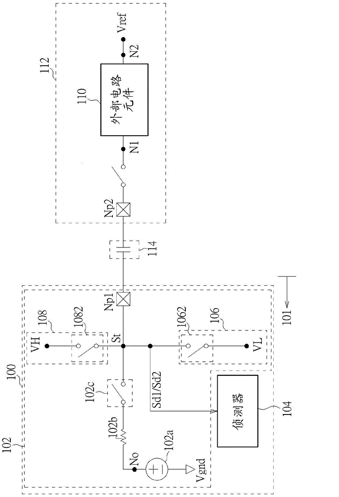
[0035] Please refer to figure 1 , figure 1 is a schematic diagram of an exemplary embodiment of the detection circuit 100 of the present invention. The detection circuit 100 is used for detecting remote connections of AC coupled applications. Specifically, in the application of AC coupling, the detection circuit 100 can determine whether the terminal circuit (such as an external resistor) is connected to the reference voltage Vref, where the reference voltage Vref can be the ground voltage Vgnd, the supply voltage Vdd or the common-mode voltage Vcm .

[0036] In the following description, the detection circuit 100 will be installed in a universal serial bus (Universal Serial Bus, USB) transmitter 101 (such as a USB3.0 transmitter), and the detection circuit 100 can be used to detect the universal serial bus transmission device 112 (such as a USB3.0 receiver). However, the present invention is not limited thereto. The detection circuit 100 can also be used in any other typ...


PUM


Abstract

A detecting circuit includes: a testing signal generator, arranged to selectively generate a testing signal having a first signal edge or a second signal edge to a connecting port; and a detector, arranged to detect a first detect signal on the connecting port after the testing signal having the first signal edge is coupled to the connecting port, and to detect a second detect signal on the connecting port after the testing signal having the second signal edge is coupled to the connecting port; wherein the detector is further arranged to determine if an external circuit element is coupled between the connecting port and a reference voltage according to the first detect signal and the second detect signal. The detecting circuit provided by the invention is capable of determining the connection situation of the external circuit element by detecting the response after the voltage on a detecting port passes the testing signals having the positive edge and the negative edge.

Description

technical field [0001] The technical field of the present invention relates to a detection circuit and a circuit detection method, especially a detection circuit and a related method for detecting the connection status of an external terminal circuit. Background technique [0002] The Universal Serial Bus (USB) is a standard interface for connecting peripheral devices and hosts. The third-generation Universal Serial Bus (USB3.0) receiver will terminate the transmission line by connecting a small resistor to ground, and by checking the termination resistor on the receiver, the transmitter can know whether Connect with another third-generation USB receiver. However, in some cases, when coupled to a transmitter, the receiver may connect the above-mentioned small resistor to the supply voltage instead of ground, and in this case, the transmitter may not be able to detect the small resistor. Therefore, it is necessary to improve the traditional method to adapt to different situ...

Claims


Application Information

Patent Timeline
Patent Type & Authority Applications(China)
IPC IPC(8): G01R31/02
CPCG01R19/00G06F11/221G06F11/2215G06F11/2247
Inventor 吴建桦赵冠华
Owner MEDIATEK INC
Why Eureka
Try Eureka