Eureka AIR delivers breakthrough ideas for toughest innovation challenges, trusted by R&D personnel around the world.

Rotating base for lamps

A technology for rotating bases and lamps, which is applied in the direction of lighting devices, parts of lighting devices, and light source fixing, etc. It can solve problems such as single structure, inconvenient adjustment of lamp angle or orientation, inconvenient carrying and installation, etc., and achieve convenient adjustment. Effect

Inactive Publication Date: 2016-08-31
NINGBO AUMA ELECTRIC TECH
View PDF6 Cites 5 Cited by
  • Summary
  • Abstract
  • Description
  • Claims
  • Application Information

AI Technical Summary

Problems solved by technology

[0002] Existing lamps can be fixed by brackets, but many brackets are fixed and have a single structure. The size of the lamps and brackets is too large, which is inconvenient to carry and install. More importantly, the angle or orientation of the lamps is inconvenient on the brackets Adjustment, which limits the lighting range of the lamp and reduces its lighting effect

Method used


Image

  • Rotating base for lamps
  • Rotating base for lamps
  • Rotating base for lamps

Examples


Embodiment Construction

[0031] The principles and features of the present invention are described below in conjunction with the accompanying drawings, and the examples given are only used to explain the present invention, and are not intended to limit the scope of the present invention.

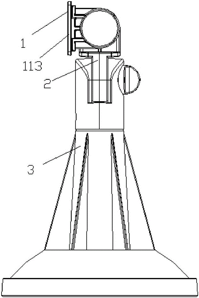
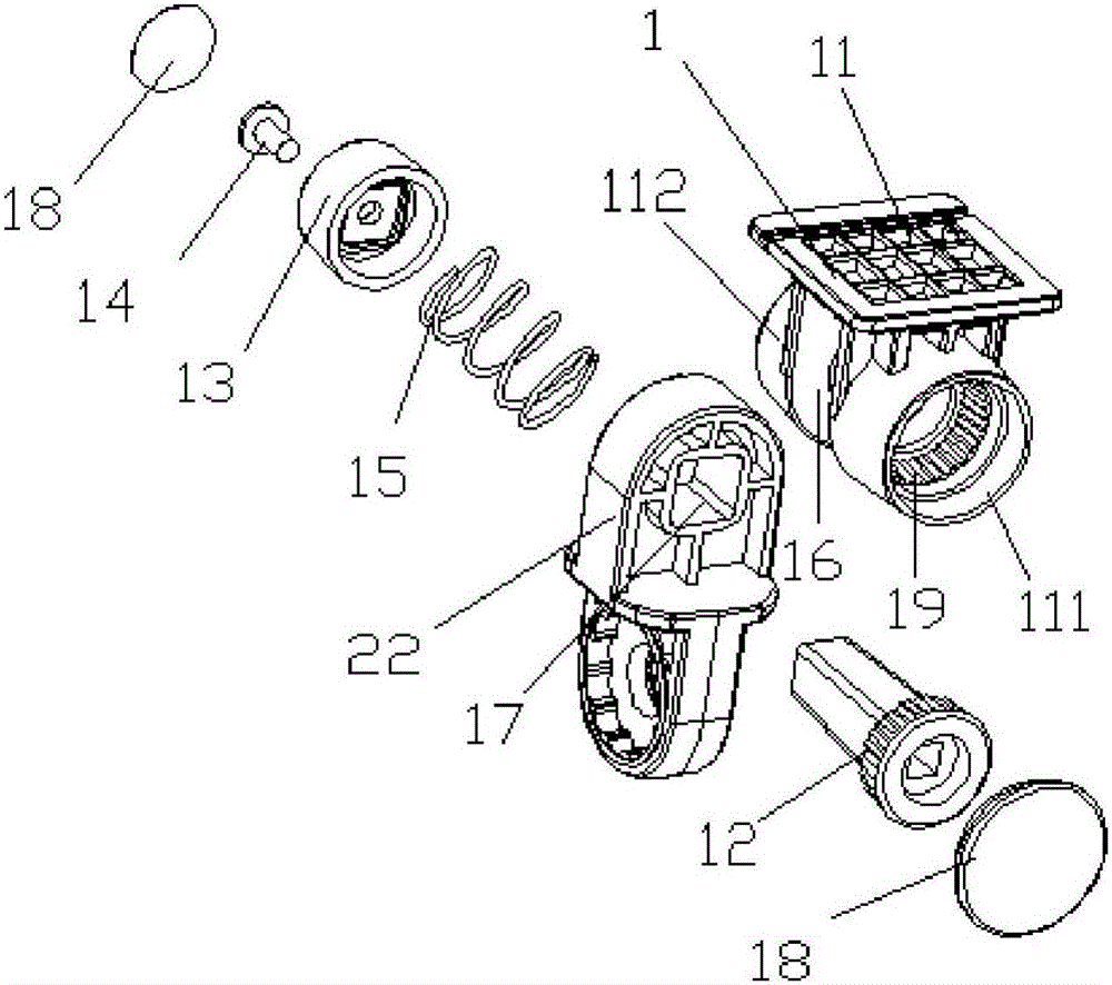
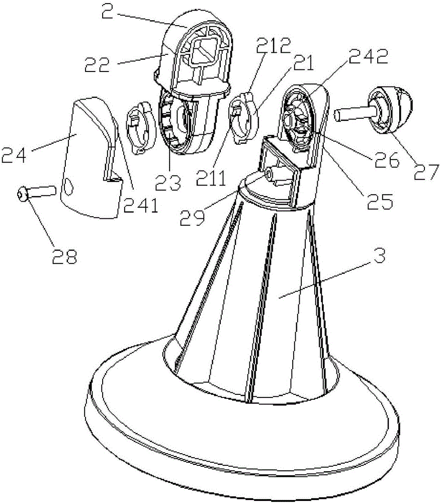
[0032] figure 1 It is a schematic diagram of the front view structure of the rotating base of the lamp of the present invention; figure 1 As shown: the rotating base of the lamp includes a base 3 and a rotating device. The rotating device includes a first rotating device 1 and a second rotating device 2. The second rotating device 2 is movably connected to the base 3, and the first rotating device 1 is movably connected to the second rotating device. On the second rotating device 2, the lamps are arranged on the first rotating device 1, and the rotating directions of the first rotating device 1 and the second rotating device 2 are perpendicular to each other.

[0033] During implementation, the lamps and lanterns a...


PUM


Abstract

The invention relates to a rotating base for lamps, comprising a base and rotating devices. The rotating devices consist of a first rotating device and a second rotating device, the second rotating device is movably connected to the base, and the first rotating device is movably connected to the second rotating device. A lamp is arranged on the first rotating device. The rotating directions of the first rotating device and the second rotating device are perpendicular to each other. The lighting angle and direction of a lamp can be adjusted conveniently. The rotating base has a simple structure, and is easy to install.

Description

technical field [0001] The invention relates to the technical field of lamp bases, in particular to a rotating base for lamps. Background technique [0002] Existing lamps can be fixed by brackets, but many brackets are fixed and have a single structure. The size of the lamps and brackets is too large, which is inconvenient to carry and install. More importantly, the angle or orientation of the lamps is inconvenient on the brackets Adjustment limits the lighting range of the lamp and reduces its lighting effect. Contents of the invention [0003] The technical problem to be solved by the present invention is to provide a rotating base of a lamp, which can conveniently adjust the lighting angle and orientation of the lamp, and has a simple structure and is easy to install. [0004] The technical solution of the present invention to solve the above technical problems is as follows: a rotating base of a lamp, including a base and a rotating device, the rotating device includ...

Claims


Application Information

Patent Timeline
Patent Type & Authority Applications(China)
IPC IPC(8): F21V21/30F21V19/00F21V14/02
CPCF21V14/02F21V19/00F21V21/30
Inventor 袁威武
Owner NINGBO AUMA ELECTRIC TECH
Why Eureka
Eureka Blog
Learn More