A large air pump
A pump and air volume technology, applied in the field of air pumps, can solve the problems of long pumping time, small air output, laborious use, etc., and achieve the effects of large pumping volume, improving pumping efficiency, and saving pumping time.
- Summary
- Abstract
- Description
- Claims
- Application Information
AI Technical Summary
Problems solved by technology
Method used
Image


Examples
Embodiment 1
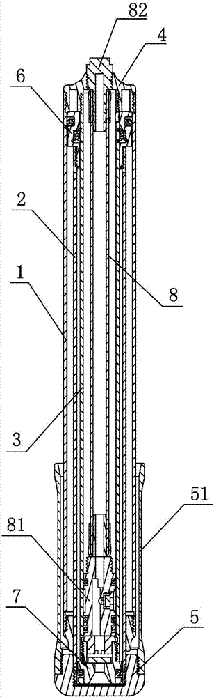
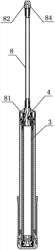
[0027] Embodiment 1: As shown in the figure, a large-capacity pump includes an outer tube 1, a middle tube 2, an inner tube 3 and an air outlet assembly that are sequentially socketed from outside to inside, and the front end of the outer tube 1 and the inner tube 3 The front ends of the front covers are respectively sealed and fixedly connected with the front cover 4, the rear end of the middle pipe 2 extends out of the rear end of the outer tube 1 and is sealed and fixedly connected with a back cover 5, and the back cover 5 is integrally arranged or screwed with a handle pipe 51, and the outer tube There is a gap between the rear end of 1 and the middle pipe 2, the front end of the middle pipe 2 is fixedly provided with a first one-way sealing piston assembly 6, the inner pipe 3 is in sealing and sliding fit with the first one-way sealing piston assembly 6, and the inner pipe 3 The lower end is fixedly provided with a second one-way sealing piston assembly 7, and the second o...
Embodiment 2
[0028] Embodiment 2: As shown in the figure, a large-capacity pump includes an outer tube 1, a middle tube 2, an inner tube 3 and an air outlet assembly that are sequentially socketed from outside to inside, and the front end of the outer tube 1 and the inner tube 3 The front ends of the front covers are respectively sealed and fixedly connected with the front cover 4, the rear end of the middle pipe 2 extends out of the rear end of the outer tube 1 and is sealed and fixedly connected with a back cover 5, and the back cover 5 is integrally arranged or screwed with a handle pipe 51, and the outer tube There is a gap between the rear end of 1 and the middle pipe 2, the front end of the middle pipe 2 is fixedly provided with a first one-way sealing piston assembly 6, the inner pipe 3 is in sealing and sliding fit with the first one-way sealing piston assembly 6, and the inner pipe 3 The lower end is fixedly provided with a second one-way sealing piston assembly 7, and the second o...
Embodiment 3
[0029]Embodiment 3: As shown in the figure, other structures are the same as Embodiment 2, the difference is that the quick connection mechanism includes a slide cover 9 and a spring 91 sleeved on the front cover 4, the slide cover 9 is slidably matched with the front cover 4, and the spring 91 is located in the slide cover 9 and connected between the front end of the front cover 4 and the inner end surface of the slide cover 9, the connector 81 is provided with a third positioning ring groove 87, and the front cover 4 is provided with a mounting hole (not shown in the figure). marked), the mounting hole is provided with an elastic support 10, the elastic support 10 includes a positioning head 101 and a support handle 102 integrally connected, there is a gap between the positioning head 101 and the mounting hole, and the positioning head 101 is embedded in the third positioning ring groove In 87, the rear end face of the positioning head 101 is an inclined plane 103, the front ...
PUM
 Abstract
Description
Claims
Application Information
 - R&D
- Intellectual Property
- Life Sciences
- Materials
- Tech Scout
- Unparalleled Data Quality
- Higher Quality Content
- 60% Fewer Hallucinations
Browse by: Latest US Patents, China's latest patents, Technical Efficacy Thesaurus, Application Domain, Technology Topic, Popular Technical Reports.
© 2025 PatSnap. All rights reserved.Legal|Privacy policy|Modern Slavery Act Transparency Statement|Sitemap|About US| Contact US: help@patsnap.com