High-impedance coaxial connector for sensor

A coaxial connector, high-impedance technology, applied in the direction of connection, two-part connection device, parts of the connection device, etc., can solve the problems of easy contact with the inner tube, easy bending, easy tilt of the glass tube, etc., to improve accuracy Performance and reliability, increased service life and frequency, convenient and quick disassembly and assembly

Active Publication Date: 2016-08-17
河北科瑞达仪器科技股份有限公司
View PDF7 Cites 6 Cited by
  • Summary
  • Abstract
  • Description
  • Claims
  • Application Information

AI Technical Summary

Problems solved by technology

[0002] Connectors for existing sensors, the male head structure is as follows figure 1 As shown, when assembling the joint, since the reference lead wire is located between the outer tube and the inner tube of the glass tube, if it is welded inside the outer tube, the lead wire of the welding machine needs to be coiled inside, which is easy to contact with the inner tube, and there is a safety hazard, so The reference lead wire needs to be bent at the end of the outer tube and then welded to the contact outer ring. The reference lead wire at the bend prevents the glass tube from being assembled to the bottom, and since the end of the glass tube cannot be equipped with a positioning slot, the glass tube is easy to tilt , so that the assembly of the male head and the glass tube is prone to angular deviation, and the waterproof and dustproof performance is poor after connection
In addition, the bending part of the reference lead is easy to disconnect, which affects the normal use of the sensor and shortens the service life of the sensor
The end of the existing male inner core is needle-shaped and easy to bend, making it impossible to insert into the female inner core, or the contact with the female inner core is not good, which affects the accuracy and reliability of the measurement data

Method used


Image

  • High-impedance coaxial connector for sensor
  • High-impedance coaxial connector for sensor
  • High-impedance coaxial connector for sensor

Examples


Embodiment Construction

[0019] Below in conjunction with accompanying drawing and specific embodiment the present invention is described in detail:

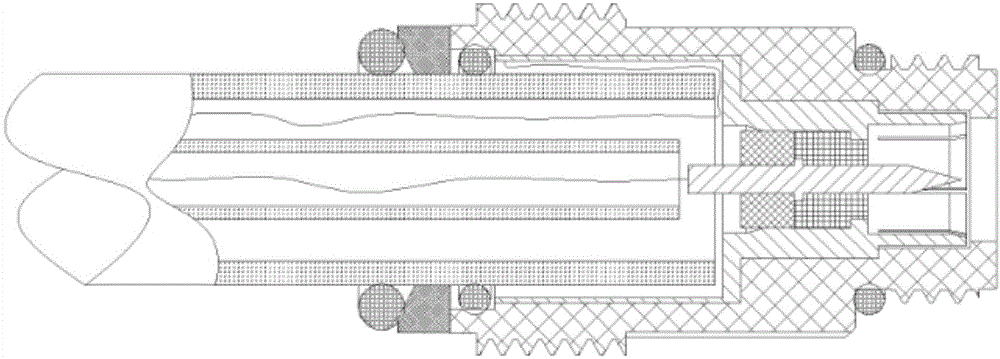
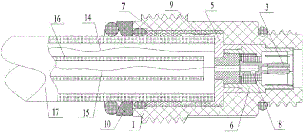
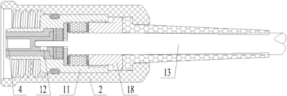
[0020] Specific examples, such as figure 2 and image 3 As shown, a high-impedance coaxial connector for sensors includes a male head and a female head. The male head includes a main body seat 1 and a contact outer ring arranged inside the main body seat 1. A male inner core 3 is arranged inside the contact outer ring , the female head includes a joint connection cap 2 and a contact inner ring arranged inside the joint connection cap 2, the inner contact ring is provided with a female head inner core 4, the cable 13 is connected to the female head inner core 4, and one end of the main body seat 1 is connected to the The glass tube forms a locking fit, and the other end of the main body seat 1 forms a locking fit with the joint connection cap 2. A sealing pressure pad 10 and a sealing ring are sequentially arranged between the main body seat 1 and the ...


PUM


Abstract

The invention discloses a high-impedance coaxial connector for a sensor. One end of a main seat is matched with a glass tube in a locked mode, the other end of the main seat is matched with a contact connecting cap in a locked mode, a contact outer ring comprises a male contact outer ring butt-joint seat and a male contact outer ring body which are arranged in sequence from outside to inside in a coaxial mode, the glass tube is sleeved with and coaxial with the male contact outer ring butt-joint seat, a wire passing hole is formed in the axis of the male contact outer ring body, a male contact inner core is located inside the male contact outer ring body, a first tin inlet is formed in the side wall, corresponding to the wire passing hole, of the male contact inner core, the first tin inlet is communicated with the wire passing hole, a reference lead is fixedly connected with the inner wall of the male contact outer ring butt-joint seat, and a measurement lead extends into the wire passing hole and is connected with the male contact inner core. After being assembled, the glass tube and a male contact form a coaxial assembly, angular defection cannot occur, after the high-impedance coaxial connector is connected, the waterproof and dustproof performance can reach level IP168, and the connector is convenient and fast to disassemble and assemble. The reference lead does not need to be bent, and the service life of the sensor is prolonged.

Description

technical field [0001] The invention belongs to the technical field of connecting devices, and relates to a connector for sensors, in particular to a high-impedance coaxial connector for sensors. Background technique [0002] Connectors for existing sensors, the male head structure is as follows figure 1 As shown, when assembling the joint, since the reference lead wire is located between the outer tube and the inner tube of the glass tube, if it is welded inside the outer tube, the lead wire of the welding machine needs to be coiled inside, which is easy to contact with the inner tube, and there is a safety hazard, so The reference lead wire needs to be bent at the end of the outer tube and then welded to the contact outer ring. The reference lead wire at the bend prevents the glass tube from being assembled to the bottom, and since the end of the glass tube cannot be equipped with a positioning slot, the glass tube is easy to tilt , so that the assembly of the male head a...

Claims


Application Information

Patent Timeline
Patent Type & Authority Applications(China)
IPC IPC(8): H01R13/52H01R13/502H01R24/42
CPCH01R13/502H01R13/5202H01R24/42
Inventor 郝拴菊郝立辉菅晓亮
Owner 河北科瑞达仪器科技股份有限公司
Why Eureka
Try Eureka