A true triaxial test fixture for dynamic disturbance rockburst simulation
A technology of dynamic disturbance and true triaxial, which is applied in the field of rock mechanics test, can solve the problems that dynamic disturbance type rockburst cannot be realized, rigid push head pressure loading cannot be applied, etc., and achieve the effect of simple structure and convenient disassembly and assembly
- Summary
- Abstract
- Description
- Claims
- Application Information
AI Technical Summary
Problems solved by technology
Method used
Image
Examples
Embodiment 1
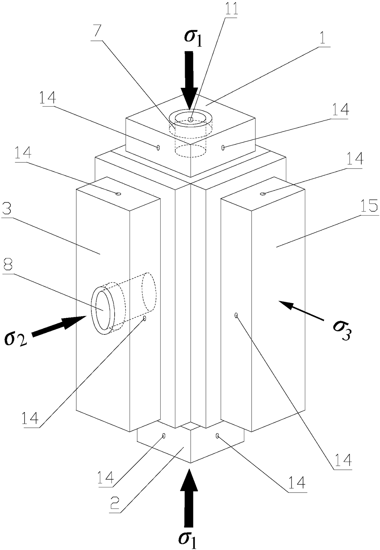
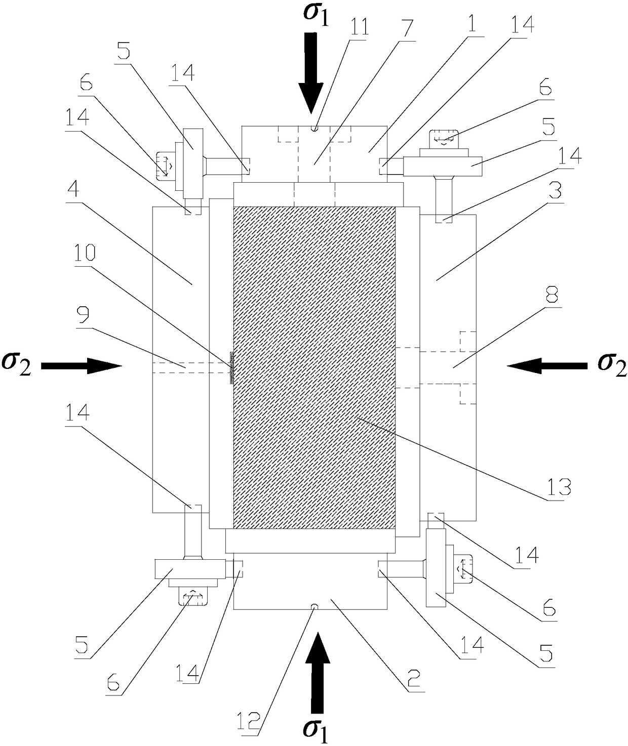
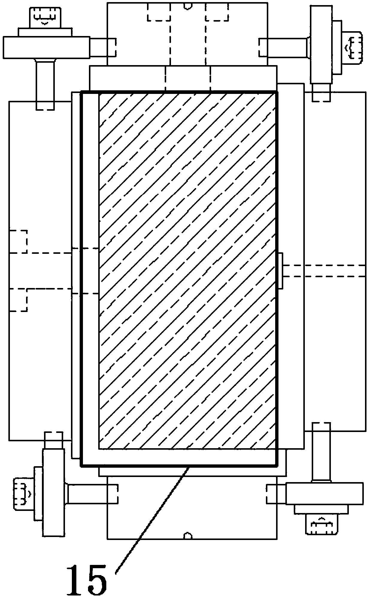
[0047] A rock sample fixture for a dynamic disturbance type true triaxial rockburst test, comprising a top pressure plate 1, a bottom pressure plate 2, a left pressure plate 4, a right pressure plate 3, a rear pressure plate 15, a horizontal disturbance rod 8, a vertical disturbance rod 7, Several common screws 6 and several U-shaped head screws 5,
[0048] A strain gauge groove 10 for placing strain gauges is opened on the contact surface between the left pressure plate 4 and the rock sample 13, and a strain gauge line through hole 9 is opened in the strain gauge groove 10,
[0049] The contact surface between the right pressure plate 3 and the rock sample 13 is provided with a horizontal disturbance rod 8 installation through hole, and the horizontal disturbance rod 8 is installed in the horizontal disturbance rod 8 installation through hole,
[0050] The contact surface between the top pressure plate 1 and the rock sample 13 is provided with a vertical disturbance rod 7 ins...
Embodiment 2
[0064] The top pressing plate 1, the bottom pressing plate 2, the left pressing plate 4, the right pressing plate 3 and the rear pressing plate 15 are respectively the top surface, the bottom surface, the left side, the right side and the rear side of the rock sample 13 in the same shape, and each side pressing plate exceeds Ninety-five percent of the area covers the corresponding surface area of the rock sample (meaning that the area of each side pressure plate is smaller than the corresponding surface area of the rock sample and greater than ninety-five percent of the corresponding surface area of the rock sample), and when installed, the top pressure plate 1 , the bottom platen 2, the left platen 4, the right platen 3 and the back platen 15 are respectively located at the center of the rock sample top surface, bottom surface, left side, right side and rear side. This is to prevent that the pressure plates on each side do not interfere with each other after the rock s...
Embodiment 3
[0068] The size of the left pressing plate 4, the right pressing plate 3 and the rear pressing plate 15 is consistent, the size of the top pressing plate 1 and the bottom pressing plate 2 are consistent, and the size of the top pressing plate 1, the bottom pressing plate 2, the left pressing plate 4, the right pressing plate 3 and the rear pressing plate 15 are larger than The size of the rock sample 13 corresponds to the top surface, bottom surface, left side, right side and rear side. During installation, the side pressure plates are combined by staggering each other to meet the movement caused by the deformation of the specimen.
[0069] The left edge and the front edge of the top pressure plate 1 are flush with the left edge and the front edge of the top surface of the rock sample 13,
[0070] The right edge and the rear edge of the bottom pressing plate 2 are flush with the right edge and the rear edge of the bottom surface of the rock sample 13,
[0071] The lower edge a...
PUM
 Abstract
Description
Claims
Application Information
 - R&D
- Intellectual Property
- Life Sciences
- Materials
- Tech Scout
- Unparalleled Data Quality
- Higher Quality Content
- 60% Fewer Hallucinations
Browse by: Latest US Patents, China's latest patents, Technical Efficacy Thesaurus, Application Domain, Technology Topic, Popular Technical Reports.
© 2025 PatSnap. All rights reserved.Legal|Privacy policy|Modern Slavery Act Transparency Statement|Sitemap|About US| Contact US: help@patsnap.com


