
Automotive suspension vibration damper energy characteristic testing system and automotive suspension vibration damper energy characteristic metering method

A technology of automobile suspension and energy characteristics, which is applied in the direction of vehicle suspension/shock absorbing mechanism testing, etc. It can solve problems such as rough automatic identification function, unfavorable mass production and testing of shock absorbers, and inability to reflect the damping characteristics of shock absorbers.

Inactive Publication Date: 2016-08-17
LIAONING UNIVERSITY OF TECHNOLOGY
View PDF10 Cites 7 Cited by
  • Summary
  • Abstract
  • Description
  • Claims
  • Application Information

AI Technical Summary

Problems solved by technology

[0005] It can be seen that relying on manual identification is not conducive to the mass production and testing of shock absorbers, and the automatic identification function of the current shock absorber dynamometer is also relatively rough.
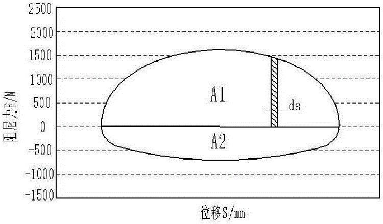
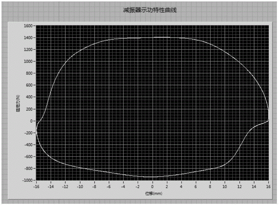
Moreover, the damping characteristics of most points tested by the shock absorber in the recovery and compression strokes cannot be reflected, and the amount of energy attenuated by the shock absorber in a round-trip stroke of the vehicle vibration is often ignored.

Method used


Image

  • Automotive suspension vibration damper energy characteristic testing system and automotive suspension vibration damper energy characteristic metering method
  • Automotive suspension vibration damper energy characteristic testing system and automotive suspension vibration damper energy characteristic metering method
  • Automotive suspension vibration damper energy characteristic testing system and automotive suspension vibration damper energy characteristic metering method

Examples


Embodiment

[0089] Embodiment Automobile suspension shock absorber energy characteristic testing system,

[0090] Such as Figure 6 and 7 The shown includes a frame body, a crank-link slider mechanism arranged on the frame body to generate sinusoidal motion, a fixture 4 for fixing the upper ring of the shock absorber 5 and a lower installation for fixing the lower ring of the shock absorber 5 during testing Bearing 6, speed sensor 9, and force sensor for measuring the damping force; the described crank-link slider mechanism is used to realize the reciprocating motion of the stretching and compression strokes of the shock absorber 5, and has a crank 10, the crank 10 One end is fixed on the frame body, and the other end of the crank 10 is connected with the bottom end of the crank connecting rod 8, and the crank connecting rod 8 can move circumferentially around the other end point of the crank 10; The mounting support 6 is connected so as to drive the shock absorber 5 to move up and down...


PUM


Abstract

The invention discloses an automotive suspension vibration damper energy characteristic testing system and an automotive suspension vibration damper energy characteristic metering method. The automotive suspension vibration damper energy characteristic testing system comprises a rack, a crank connecting rod slide block mechanism which is arranged on the rack and can generate sine movement, a clamp for fixing a vibration damper, a lower mounting bracket, a speed sensor, and a force sensor for measuring a damping force. The crank connecting rod slide block mechanism is used for realizing reciprocating motion between a stretching stroke and a compression stroke of the vibration damper and is provided with a crank, wherein a crank connecting rod can perform circumferential motion around the other end point of the crank. The top end of the crank connecting rod is connected with the lower mounting bracket, thereby driving the vibration damper to perform vertical movement along with the crank connecting rod, wherein a slider is driven by the crank connecting rod and performs up-and-down motion. The metering method is based on the automotive suspension vibration damper energy characteristic testing system, wherein computer image identification technology is applied on solving and calibration for vibration damper indicator diagram. Furthermore the metering method is a quantitative analyzing method for energy absorbed by the vibration damper, thereby supplying a new evaluation method and a quantification standard for performance testing of the vibration damper.

Description

technical field [0001] The invention relates to the field of automobile suspension shock absorbers, in particular to an energy characteristic testing system and measurement method of automobile suspension shock absorbers. Background technique [0002] The shock absorber is the main damping element in the automobile suspension, which is installed in parallel with the elastic element, and its performance is directly related to the comfort and safety of the automobile. Automobile suspension is the key assembly to ensure the ride comfort and operational stability of the automobile, and the shock absorber, as the core component, bears a very large responsibility. Therefore, it is very necessary to study the performance and failure modes of automobile shock absorbers, no matter for the inspection before leaving the factory or the maintenance in the future. [0003] Shock absorbers need to be tested to clarify their performance during production and maintenance. The performance o...

Claims


Application Information

Patent Timeline
Patent Type & Authority Applications(China)
IPC IPC(8): G01M17/04
CPCG01M17/04
Inventor 王天利田雪曾庆东王雪杨旭光
Owner LIAONING UNIVERSITY OF TECHNOLOGY
Learn More