Card combination connection device and electronic equipment

A technology that combines connection and electronic equipment, applied in the parts of the connection device, coupling device, connection, etc., can solve problems such as damage to electronic equipment, and achieve the effect of improving experience and efficiency

Inactive Publication Date: 2016-08-03
VIVO MOBILE COMM CO LTD
View PDF5 Cites 2 Cited by
  • Summary
  • Abstract
  • Description
  • Claims
  • Application Information

AI Technical Summary

Problems solved by technology

[0003] The embodiment of the present invention provides a card combination connection device and electronic equipment, which can solve the problem that the user takes off the card tray and inserts it directly into the smart card or inserts the card tray backwards to cause damage to the electronic equipment during use.

Method used


Image

  • Card combination connection device and electronic equipment
  • Card combination connection device and electronic equipment
  • Card combination connection device and electronic equipment

Examples


Embodiment 1

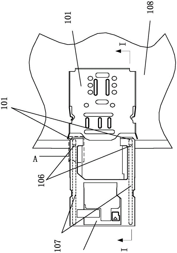
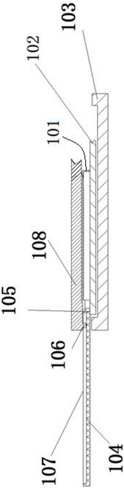
[0015] Please refer to Figure 1 to Figure 4 , the electronic device provided by Embodiment 1 of the present invention includes: a first housing 108, a second housing 103, a card tray 104, a card holder and a bracket 101, and the card holder and the bracket 101 form an inner cavity, and the card holder 104 is included sliding in the cavity. The card tray 104 , the card holder and the bracket 101 are placed in the space enclosed by the first housing 108 and the second housing 103 .

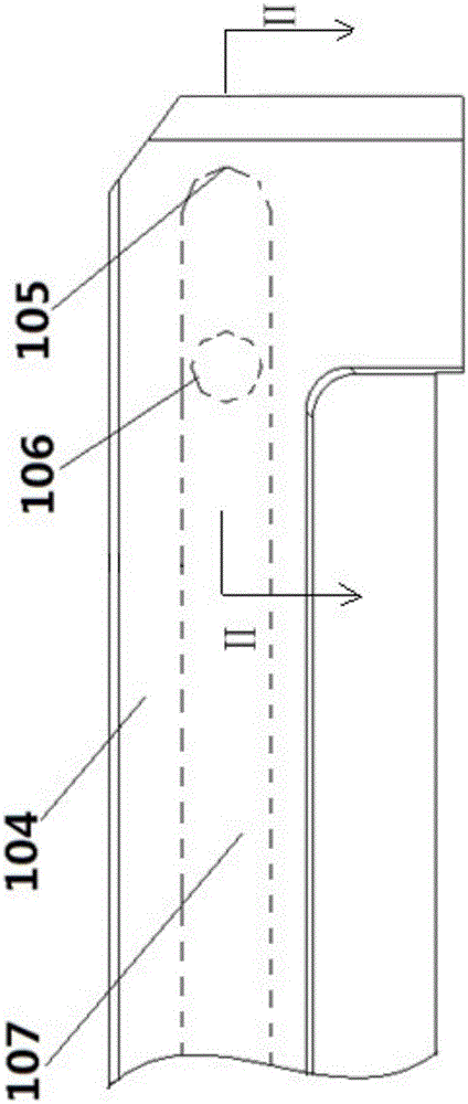
[0016] Such as figure 1 As shown, the end of the card tray 104 inserted into the inner cavity is provided with a limiting portion 105 , and the first housing 108 is provided with a locking portion 106 that cooperates with the limiting portion 105 and limits the extraction of the card tray 104 .

[0017] Further, the cartridge is welded and fixed on the circuit main board 102 , and the circuit main board 102 is arranged on the second casing 103 .

[0018] The card holder and the bracket 101 are i...

Embodiment 2

[0027] Please refer to Figure 5 The difference between the electronic device provided by Embodiment 2 of the present invention and Embodiment 1 is that: the guide groove 207 is a semi-closed chute, so that the clamping portion 206 can be arranged in more shapes, such as a columnar boss, a letter J shape Boss, letter U-shaped boss, etc. A semi-closed chute means that one side of the chute does not have a side wall, so that the clamping part 206 extends above the bottom of the guide groove 207 . When the above-mentioned clamping part 206 is a letter J-shaped boss, a concave top surface is formed at the bent position, and the concave top surface is used as a matching guide rail surface, and the bottom surface of the above-mentioned guide groove 207 is used as another matching guide rail In the process of pushing and pulling the card tray 204, the two guide rail surfaces can come into sliding contact with each other. The card holder 204 is in sliding contact with the bottom sur...


PUM


Abstract

The present invention provides a card combination connection device and electronic equipment, which relate to the technical field of electronic hardware. The card combination connection device includes: a card holder, a card holder and a bracket located above the card holder. It is characterized in that the card The seat and the bracket form an inner cavity, the card holder slides in a drawer type in the inner cavity, a limit part is provided at one end of the card holder inserted into the inner cavity, and the housing or the card holder is set There is a holding part that cooperates with the limiting part and restricts the pulling out of the card tray. The electronic equipment includes a circuit main board, and also includes the above-mentioned card combination connection device, and the card holder and the bracket are both fixedly connected to the circuit main board. It solves the problem that the user removes the card tray and inserts it directly into the smart card or inserts the card tray backwards to cause damage to the electronic device during use.

Description

technical field [0001] The invention relates to the technical field of electronic equipment, in particular to a card combination connection device and electronic equipment. Background technique [0002] With the continuous development of mobile devices, mobile devices are getting thinner and thinner, non-removable batteries are becoming more and more popular, and smart card trays are also frequently appearing on flagship phones of various brands. However, in the process of use, the user often takes off the card holder and directly inserts the smart card or inserts it backwards when the card holder is inserted, causing the card holder of the smart card to be damaged and thus invalid. Contents of the invention [0003] Embodiments of the present invention provide a card combination connection device and electronic equipment, which can solve the problem that the user removes the card tray and inserts it directly into the smart card or inserts the card tray backwards to cause ...

Claims


Application Information

Patent Timeline
Patent Type & Authority Applications(China)
IPC IPC(8): H01R12/71H01R13/629H01R13/502
Inventor 刘瑞轩王海亮徐国伟
Owner VIVO MOBILE COMM CO LTD
Why Eureka
Try Eureka