A circular movable led light mechanism

A LED lamp and ring-shaped technology, which is applied to components of lighting devices, semiconductor devices of light-emitting elements, lighting and heating equipment, etc. It can solve the problems that the irradiation range and irradiation angle cannot be adjusted, and cannot meet the different needs of users.

Active Publication Date: 2018-06-19
江门市迈菲特光电科技有限公司
View PDF3 Cites 0 Cited by
  • Summary
  • Abstract
  • Description
  • Claims
  • Application Information

AI Technical Summary

Problems solved by technology

[0002] Existing LED lamps are generally directly fixed at one position, and the irradiation range and irradiation angle cannot be adjusted, which cannot meet the different needs of users, so it is necessary to improve

Method used


Image

  • A circular movable led light mechanism
  • A circular movable led light mechanism
  • A circular movable led light mechanism

Examples


Embodiment Construction

[0026] The specific embodiments of the present invention will be described in further detail below in conjunction with the drawings and embodiments. The following examples are used to illustrate the present invention, but not to limit the scope of the present invention.

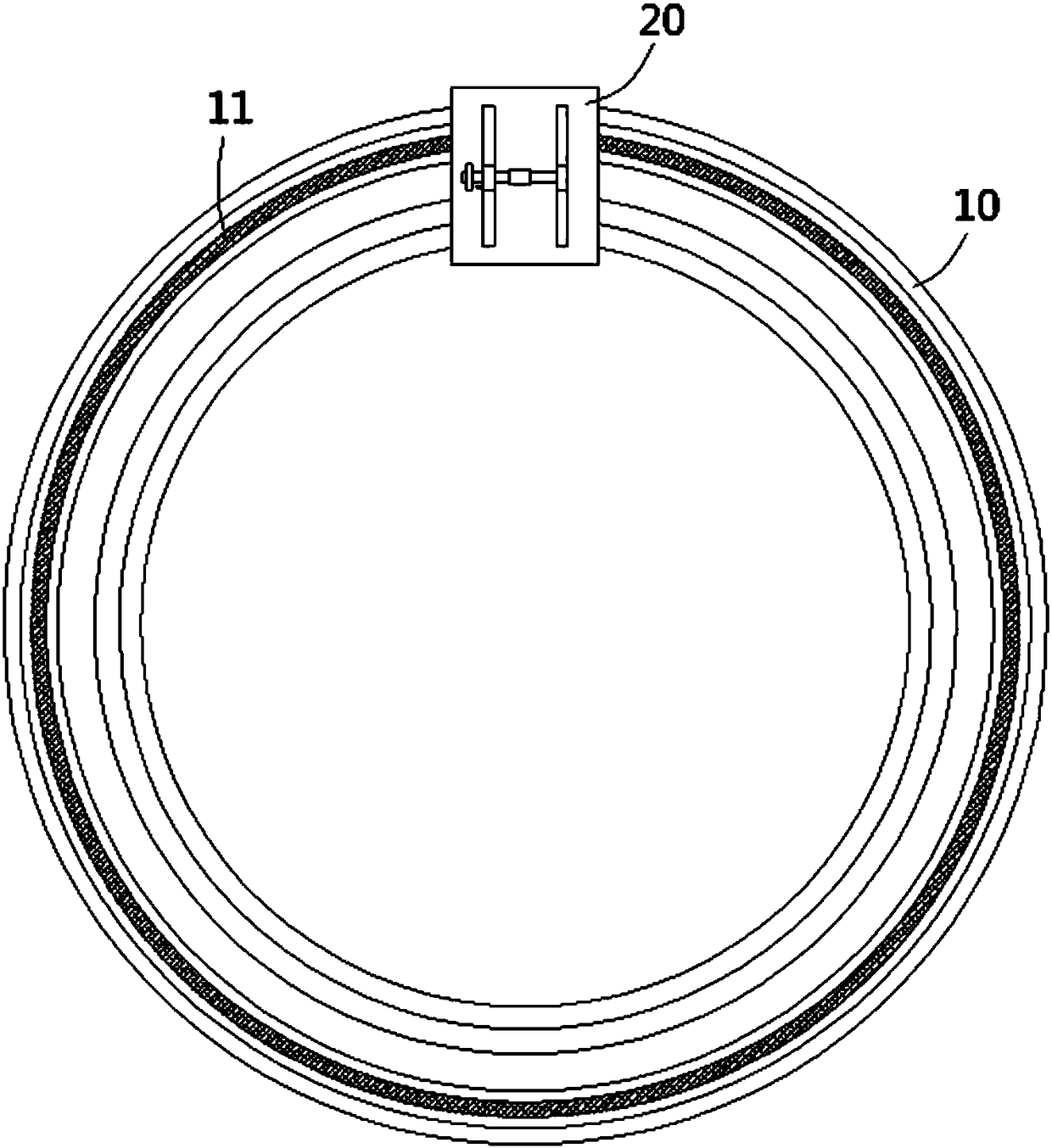
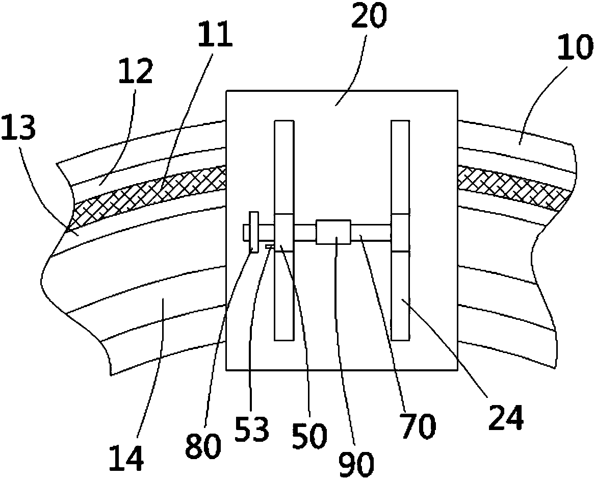
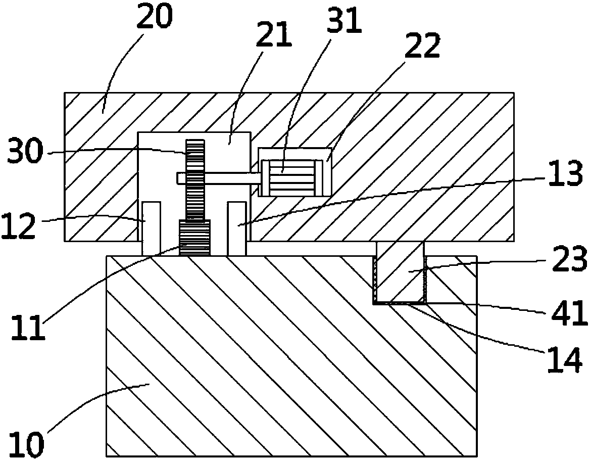
[0027] See Figure 1 to Figure 3 , The circularly movable LED lamp mechanism of the present invention includes a circular rail 10 on which is provided with a lamp holder 20, the top surface of the circular rail 10 has a circular rack portion 11, and the lamp holder An arc-shaped inserting groove 21 is formed on the bottom surface of 20, and the rack portion 11 is inserted into the inserting groove 21, and a first protective plate 12 is formed on the annular rails 10 on the front and back sides of the rack portion 11 And the second protective plate 13, the first protective plate 12 and the second protective plate 13 are ring-shaped and higher than the rack portion 11, the first protective plate 12 and the second...


PUM


Abstract

The invention discloses an LED lamp mechanism capable of moving annularly. The LED lamp mechanism capable of moving annularly comprises an annular track, wherein a lamp seat is arranged on the annular track; an annular rack part is arranged on the top surface of the annular track; an arc-shaped inserting groove is formed in the bottom surface of the lamp seat; the rack part is inserted in the inserting groove; a transmission gear is hinged to the inside of the inserting groove and is engaged with the rack part; a pair of elongated moving grooves is formed in the top surface of the lamp seat; a pair of vertical plates is inserted in the moving grooves; the lower ends of the pair of vertical plates are fixedly connected with each other through a connecting strip; an elongated middle groove is formed in the lamp seat; the connecting strip is inserted in the middle groove; an outer spline shaft is hinged to the upper ends of the vertical shafts; one end of the outer spline shaft extends out of one of the vertical plates and an adjusting plate fixedly sleeves the end of the outer spline shaft; a lamp shell sleeves the outer spline shaft between the two vertical plates; and an LED lamp is arranged in the lamp shell. The illumination range and the illumination angle of the LED lamp can be adjusted so as to meet different using demands.

Description

Technical field: [0001] The invention relates to the technical field of LED lamp manufacturing, in particular to an LED lamp mechanism capable of circular movement. Background technique: [0002] The existing LED lights are generally directly fixed at a position, and the irradiation range and the irradiation angle cannot be adjusted, which cannot meet the different needs of users, and it is necessary to improve. Summary of the invention: [0003] The purpose of the present invention is to solve the problems existing in the prior art, and to provide an LED lamp mechanism capable of adjusting the irradiation range and the irradiation angle of the LED lamp, so as to meet different needs of use. [0004] The present invention relates to a circularly movable LED lamp mechanism, comprising a circular track on which a lamp holder is provided, the top surface of the circular rail has a circular rack part, and an arc is formed on the bottom surface of the lamp holder The rack part is insert...

Claims


Application Information

Patent Timeline
Patent Type & Authority Patents(China)
IPC IPC(8): F21S8/00F21V14/02F21V21/34F21Y115/10
CPCF21S8/00F21V14/02F21V21/34
Inventor 付淑珍
Owner 江门市迈菲特光电科技有限公司
Why Eureka
Try Eureka