
A shale gas pipeline system

A technology for transporting pipelines and shale gas, which is applied in pipeline systems, pipeline supports, pipes/pipe joints/fittings, etc., and can solve the problems of difficulty in quickly judging the leakage location, waste of shale gas leakage, and poor shock absorption effect. , to achieve the effect of simple structure, preventing leakage and improving shock absorption effect

Inactive Publication Date: 2018-10-16
YANGTZE NORMAL UNIVERSITY
View PDF7 Cites 0 Cited by
  • Summary
  • Abstract
  • Description
  • Claims
  • Application Information

AI Technical Summary

Problems solved by technology

[0004] The existing shale gas pipeline installation is generally fixed directly on the installation frame with a structure similar to a hoop device, which has poor shock absorption effect, and long-term use may easily cause the pipeline to leak due to long-term vibration and impact
Especially for some aging pipeline sections with long service life, if leakage occurs due to various reasons, it will not only cause waste of shale gas leakage, but also easily lead to explosion accidents
Moreover, when a shale gas pipeline leaks, it is difficult to quickly determine the location of the leak by visual inspection. Therefore, how to better detect and judge the leakage of shale gas pipelines, so as to facilitate and quickly repair leaks to ensure safety, has become an issue to be considered. The problem

Method used


Image

  • A shale gas pipeline system
  • A shale gas pipeline system
  • A shale gas pipeline system

Examples


Embodiment approach

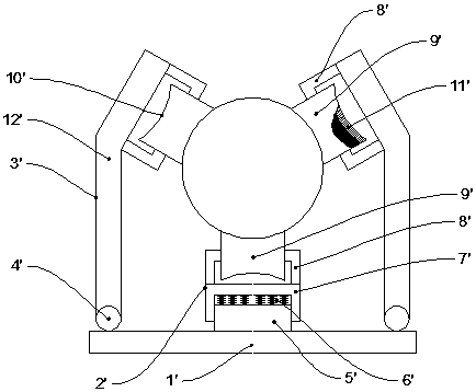
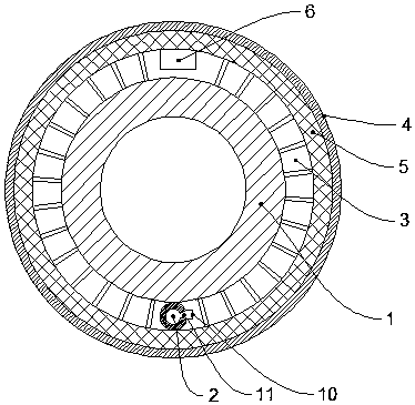
[0040] The optimal implementation mode: if Figure 1-3 As shown, a shale gas transmission pipeline system includes a shale gas pipeline anti-leakage section. A leak detection structure is also provided.

[0041] Among them, at least two fitting supports 9' arranged around the circumference of the shale gas pipeline are installed on the mounting bracket, and one side of the fitting supports 9' is used to fit the surface of the shale gas pipeline to realize the alignment of the shale gas pipeline. The support is fixed and the side surface is provided with an elastic shock-absorbing layer 11'.

[0042] In this way, it is possible to rely on the elastic shock-absorbing layer that fits the support to realize the fit and support of the shale gas pipeline, rely on its elasticity to achieve a shock-absorbing effect, and prolong the service life of the pipeline.

[0043] Wherein, there are three fitting supports 9' and they are evenly arranged around the circumference of the shale ga...


PUM


Abstract

The invention discloses a shale gas conveying pipeline system. The shale gas conveying pipeline system comprises a shale gas pipeline leakage preventing section, and is characterized in that the two ends of the shale gas pipeline leakage preventing section are arranged and fixed through installing supports, a damping installing structure is formed, and a leakage detecting structure is further arranged outside the shale gas pipeline leakage preventing section. The shale gas conveying pipeline system has the beneficial effects that the structure is simple, the damping effect can be improved so as to prevent leakage, when leakage happens, the pipeline leakage situation can be rapidly and accurately reflected so that rapid leakage repairing can be convenient, and safety is improved.

Description

technical field [0001] The invention relates to the field of a shale gas transmission pipeline system, in particular to a shale gas transmission pipeline system. Background technique [0002] Shale gas refers to the reserves in the shale formation Natural gas resources available for exploitation are a new type of clean energy. my country has abundant shale gas reserves and broad application prospects. [0003] In the transportation process after shale gas mining, various factors will cause the vibration of the pipeline due to the instability of air pressure during the mining process of shale gas, and the high pressure transportation is generally used in the transportation process. It mainly includes pipeline vibration caused by gas column natural frequency, mechanical natural frequency, gas flow pulsation and liquid hammer vibration, and the direction of the gas pipeline during vibration is uncertain. [0004] The existing shale gas pipeline installation is generally fixed...

Claims


Application Information

Patent Timeline
Patent Type & Authority Patents(China)
IPC IPC(8): F16L3/02F17D5/02F16F15/04
CPCF16F15/04F16L3/02F17D5/02
Inventor 刘合敏
Owner YANGTZE NORMAL UNIVERSITY
Learn More