
River silt vacuum dehydration treatment vehicle

A vacuum dehydration and river sludge technology, which is applied in water/sludge/sewage treatment, dehydration/drying/concentrated sludge treatment, special treatment targets, etc. It can solve the problems of low work efficiency and poor treatment effect, and achieve easy operation Effect

Active Publication Date: 2018-05-25
浙江工业大学工程设计集团有限公司 +2
View PDF7 Cites 0 Cited by
  • Summary
  • Abstract
  • Description
  • Claims
  • Application Information

AI Technical Summary

Problems solved by technology

[0004] In order to overcome the shortcomings of low working efficiency and poor treatment effect of the existing river silt treatment methods, the present invention provides a river silt vacuum dehydration treatment vehicle with high working efficiency and good treatment efficiency

Method used


Image

  • River silt vacuum dehydration treatment vehicle
  • River silt vacuum dehydration treatment vehicle
  • River silt vacuum dehydration treatment vehicle

Examples


Embodiment Construction

[0017] The present invention will be further described below in conjunction with the accompanying drawings.

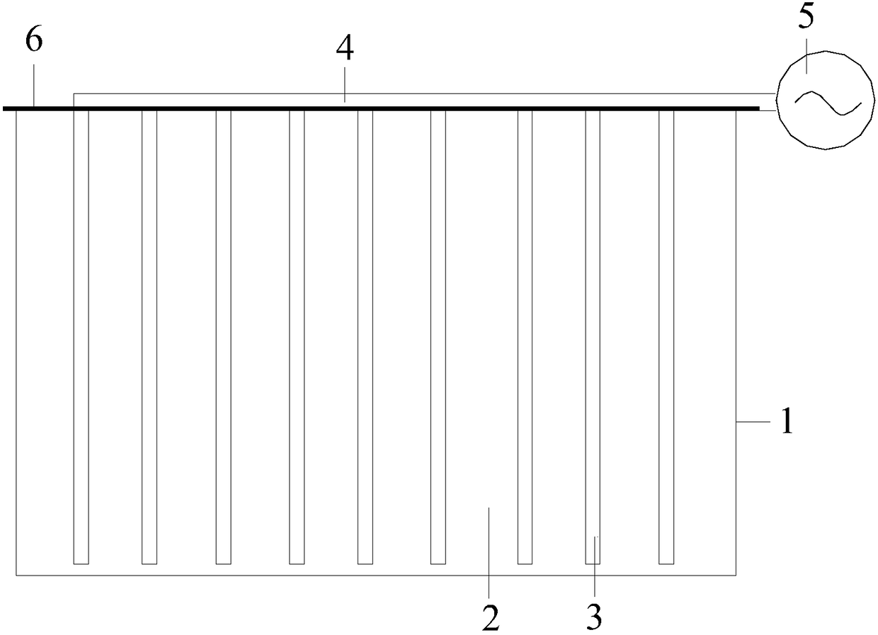
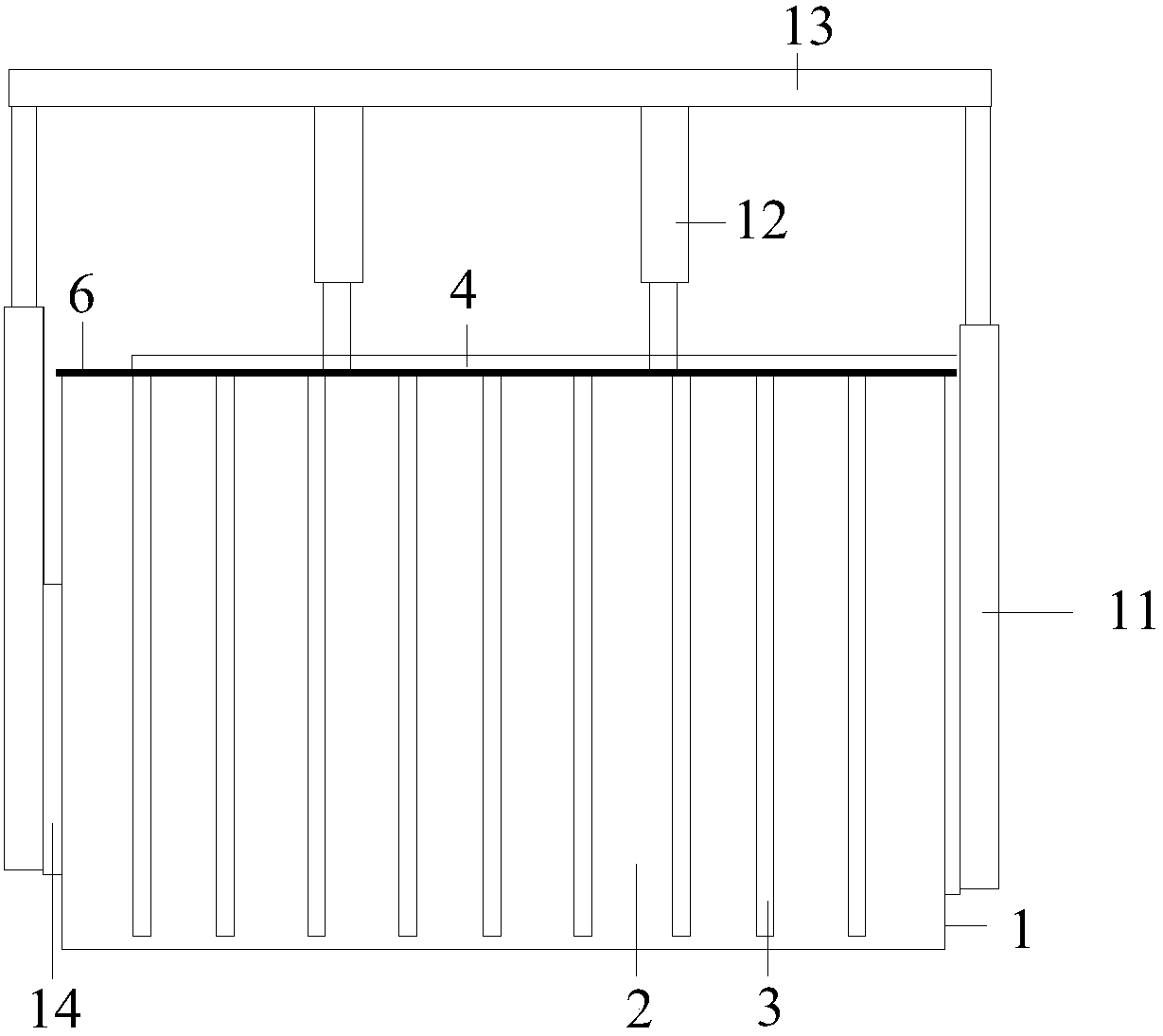
[0018] refer to Figure 1 ~ Figure 4 , a river sludge vacuum dehydration treatment vehicle, including a vehicle body, the vacuum dehydration treatment vehicle also includes a vacuum sludge tank 1 and a drainage mechanism, the drainage mechanism includes a vacuum pump 5, a horizontal pipe 4 and a plurality of sets of vertical drainage pipes 3, The outlet of the vacuum pump 5 communicates with one end of the horizontal pipe 4, and the multiple groups of vertical drainage pipes 3 are arranged side by side on the horizontal pipe 4, and the top surface of the vacuum sludge tank 1 is provided with the multiple A through hole into which a group of vertical drain pipes are inserted, and a sealing ring is provided at the connection between the vertical drain pipe and the through hole.

[0019] A sealing ring is provided at the connection between the through hole on the top of ...


PUM


Abstract

A river sludge vacuum dehydration treatment cart comprises a cart body, and further comprises a vacuum sludge tank and a drainage mechanism.The drainage mechanism comprises a vacuum pump, a horizontal pipe and multiple sets of vertical drainage pipes.An outlet of the vacuum pump is communicated with one end of the horizontal pipe, the vertical drainage pipes are arranged on the horizontal pipe side by side, through holes for the vertical drainage pipes to be inserted in are formed in the top face of the vacuum sludge tank, and sealing rings are arranged at the connecting positions of the vertical drainage pipes and the through holes.The river sludge vacuum dehydration treatment cart is high in working efficiency and good in treatment effect.

Description

technical field [0001] The invention relates to a river sludge vacuum dehydration treatment vehicle. Background technique [0002] In our country, there are a huge number of widely distributed small rivers and small lakes that are seriously polluted by silting and need to be treated. First of all, they must be dredged. The traditional river dredging method is to use a marine grab crane to grab the silt from the river, put it on a transport ship and transport it to a designated place for centralized storage. This treatment method not only causes serious secondary water pollution during the mud grabbing process , and the water content of the silt is extremely high, the amount of transportation and disposal is also large, and a large storage yard is required to occupy land. For those small rivers and small lakes that are seriously silted up, even if this traditional method is adopted, dredging ships cannot be driven in, and transport ships cannot operate because the water dept...

Claims


Application Information

Patent Timeline
Patent Type & Authority Patents(China)
IPC IPC(8): C02F11/12B01D29/56
CPCB01D29/56C02F11/12C02F2303/06
Inventor 章雪峰杨俊杰单玉川闻卫东任海刚郑丽海傅林峰
Owner 浙江工业大学工程设计集团有限公司
Learn More