
Ball hydraulic elevator

A lift, hydraulic technology, applied in the field of lifts, can solve the problems of inability to achieve order prohibition, no brake control, etc., and achieve the effect of convenient implementation and simple operation.

Active Publication Date: 2016-07-20
SUZHOU COMPORT HYDRAULIC ELEVATORING MACHINERY CO LTD
View PDF5 Cites 8 Cited by
  • Summary
  • Abstract
  • Description
  • Claims
  • Application Information

AI Technical Summary

Problems solved by technology

[0004] However, when the conveying roller table is passively rotating (each conveying roller rotates on its own), there is no brake control. Under the action of inertia, no external force is applied to the product, and the conveying rollers still continue to rotate, resulting in the inability to achieve the effect of prohibition during the conveying process.

Method used


Image

  • Ball hydraulic elevator

Examples


Embodiment Construction

[0021] The present invention will be further described below in conjunction with the embodiments shown in the accompanying drawings.

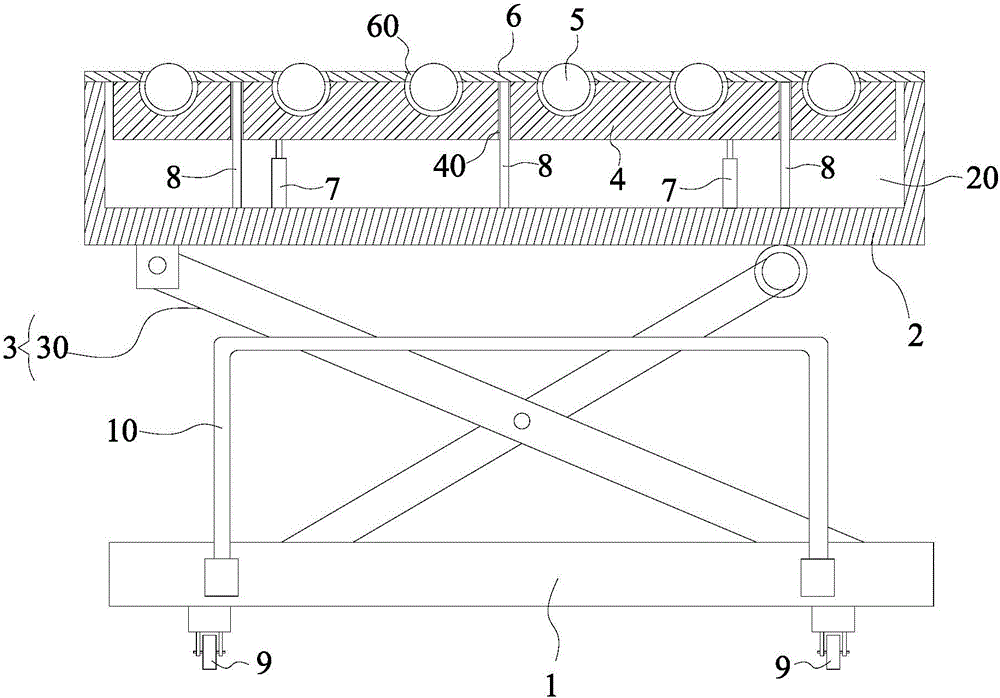
[0022] Such as figure 1 As shown, the ball hydraulic elevator provided in this embodiment includes a base 1, a carrying platform 2, and a lifting mechanism 3. The carrying platform 2 is provided with a groove 20 with the opening facing upwards, and the elevator also includes a And the mounting seat 4 that can be lifted up and down along the height direction of the groove 20, a plurality of balls 5 that are arranged on the mounting seat 4 and can roll freely, and have an escape hole 60 for the upper surface of the ball 5 to pass through and open the groove 20 Closed cover plate 6, wherein the upper surface of a plurality of balls 5 is set flush, when the balls 5 are required to convey materials, the mounting seat 4 rises, and the balls 5 pass through the avoidance hole 60 and emerge from the upper surface of the cover plate 6; when needed When ...


PUM


Abstract

The invention relates to a ball hydraulic elevator. The ball hydraulic elevator comprises a base, a bearing platform and a lifting mechanism, wherein a groove of which an opening is arranged upwards is formed in the bearing platform; the elevator also comprises a mounting base, a plurality of balls and a cover plate; the mounting base is positioned in the groove and can vertically lift along the height direction of the groove; the balls are arranged on the mounting base and can freely roll; the cover plate is proved with avoiding holes for upper surface of the balls to penetrate through and is used for closing the opening of the groove; the upper surfaces of the balls are arranged to be flush; when the balls need to be used for conveying materials, the mounting base ascends, the balls penetrate through the avoiding holes and protrude out of the upper surface of the cover plate; and when the balls need to be stopped conveying the materials, the mounting base descends, the balls retract into the avoiding holes, and the materials are stood on the cover plate. According to the ball hydraulic elevator disclosed by the invention, by contacting and separating the balls and the materials, the conveying of the materials is realized; and meanwhile, an effect of strict enforcement can be realize. The ball hydraulic elevator has the advantages of high practicality, simplicity in operation and convenience in implementation.

Description

technical field [0001] The invention belongs to the field of lifts, in particular to a ball hydraulic lift. Background technique [0002] Elevators are widely used in factories, hotels, restaurants, stations, airport theaters, exhibition halls and other places. They are the best safe companions for maintenance of machinery, paint decoration, replacement of lamps, electrical appliances, cleaning and maintenance, etc. [0003] At present, with the continuous development of assembly line operations and automation, the application of elevators is very common, such as roller-type elevators, which mainly include a base, a carrying platform, a lifting mechanism between the base and the carrying platform, and a lift on the carrying platform. Conveyor roller table, wherein the continuous operation is realized by the transfer or transfer of the conveyor roller table. [0004] However, when the conveying roller table is passively rotating (each conveying roller rotates on its own), th...

Claims


Application Information

Patent Timeline
IPC IPC(8): B66F7/08B66F7/28
CPCB66F7/065B66F7/08B66F7/28
Inventor 庄慧琴朱福明陆志强曹剑良
Owner SUZHOU COMPORT HYDRAULIC ELEVATORING MACHINERY CO LTD
Learn More