Sliding straight line drawing device and multi-line stakeout method using the device

A sliding, straight-line technology, applied in workshop equipment, manufacturing tools, etc., can solve the problems of complex line drawing method, increase the error value of axis or edge, and large amount of ink, so as to improve the lofting efficiency, high efficiency, Simple to use effects

Active Publication Date: 2018-01-26
CHINA METALLURGICAL CONSTR ENG GRP
View PDF11 Cites 0 Cited by
  • Summary
  • Abstract
  • Description
  • Claims
  • Application Information

AI Technical Summary

Problems solved by technology

Since the distance between the positioning points of building components is relatively large, generally more than ten meters or more than tens of meters, and the ink line installed in the ink fountain is not too long, it is necessary to divide the axis into several sections, and use the ink fountain to divide it into several sections. Pop up the continuous axis, and then use the edge positioning points separated by the axis to pop up the continuous edge several times, which increases the workload of technicians and increases the error value of the axis or edge
[0004] In addition, the existing line drawing tools are all aimed at engineering or blackboard drawing, and there is no line drawing tool suitable for building construction
On the other hand, the straight line of the architectural drawing line is long, requires a large amount of ink, and needs to draw multiple straight lines with different spacing at the same time. Generally, the drawing line in the engineering line drawing tool or the blackboard line drawing tool can only draw a straight line, and cannot be used directly. draw lines in engineering
Moreover, the structure of the existing line-drawing tools is relatively complicated, and the method of drawing lines is also relatively complicated.

Method used


Image

  • Sliding straight line drawing device and multi-line stakeout method using the device
  • Sliding straight line drawing device and multi-line stakeout method using the device

Examples


Embodiment

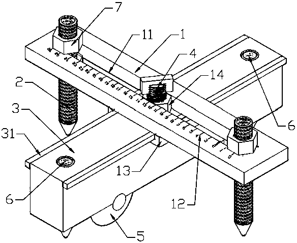
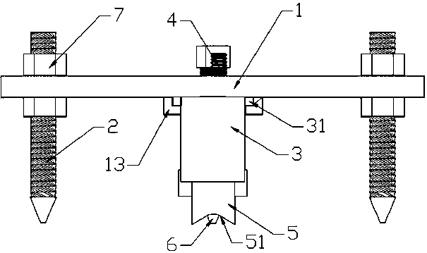
[0027] As shown in the figure, as shown in the figure, the sliding straight line drawing device provided by this embodiment includes a scale plate 1 with a transverse chute 11 in the middle, and two chute 11 are symmetrically arranged on the scale plate 1. An ink pen 2 that can be placed on the upper limit of the scale plate 1; a marking block 3 with a roller 5 at the bottom is provided under the scale plate 1, and the marking block 3 and the scale plate 1 are vertically intersecting, and the rollers The rolling paths of 5 are all perpendicular to the length direction of the chute 11; on the scale plate 1, the upper side and / or the lower side of the chute 11 are provided with a row of marking lines 12 for marking the length, and the starting and ending points of the marking lines 12 are is the start and end point of the chute.

[0028] If the reticle block 3 is fixedly arranged under the scale plate 1, a dead angle for drawing lines will occur because of the blocking of the re...


PUM


Abstract

The invention discloses a sliding type straight line drawing device and a multi-straight-line layout method adopting the sliding type straight line drawing device. The line drawing device comprises a scaleplate with a transverse sliding groove in the middle, and ink pens which are arranged in the sliding groove and can be limited on the scaleplate are arranged on the scaleplate. A line marking block with rollers at the bottom is arranged below the scaleplate, and the rolling paths of the rollers are both perpendicular to the length direction of the sliding groove. A row of marking lines for marking the length is arranged at the position, on the upper side and / or the lower side of the sliding groove, of the scaleplate, and the starting point and ending point of the marking lines are the starting point and ending point of the sliding groove. The layout method comprises the specific steps that the starting point for line drawing is marked; the number of the needed ink pens, the distance between the adjacent ink pens and / or the distance between the ink pens and a line marking pen are determined; the ink pens are mounted; and the line marking block is pushed to draw a line. The sliding type straight line drawing device is simple in structure, multiple straight lines can be drawn at the same time, and a line drawing method adopting the device has the beneficial effects of being convenient to operate and high in efficiency.

Description

technical field [0001] The invention belongs to the field of building construction, and in particular relates to a sliding type straight line drawing device and a multi-line stakeout method using the device. Background technique [0002] During the construction process, the construction technicians need to stake out the dimensions marked on the walls, columns, and beams on the construction drawings to the leveled cushion or concrete slab according to the positioning points of the building components given by the surveyors, so as to prepare for the subsequent Create conditions for steel bar binding and formwork closing. [0003] Usually, when setting out, construction technicians first draw a straight line between two positioning points, use the ink fountain commonly used by carpenters to pop up the axis, and then use a steel ruler to mark the sidelines of walls, columns, and beams according to the axis. Since the distance between the positioning points of building component...

Claims


Application Information

Patent Timeline
Patent Type & Authority Patents(China)
IPC IPC(8): B25H7/04
CPCB25H7/04
Inventor 邱长林何俨杨洋张元洪聂俊宵
Owner CHINA METALLURGICAL CONSTR ENG GRP
Why Eureka
Try Eureka