
Single-output-shaft hub-type DC brushless motor

A DC brushless motor and hub-type technology, applied in the direction of electrical components, electromechanical devices, electric components, etc., can solve problems such as damage, poor rim sealing, low assembly efficiency, etc., to ensure reliability in use, good sealing performance, and extended The effect of service life

Inactive Publication Date: 2016-07-13
CHANGZHOU QIYU ELECTRONICS TECH
View PDF13 Cites 3 Cited by
  • Summary
  • Abstract
  • Description
  • Claims
  • Application Information

AI Technical Summary

Problems solved by technology

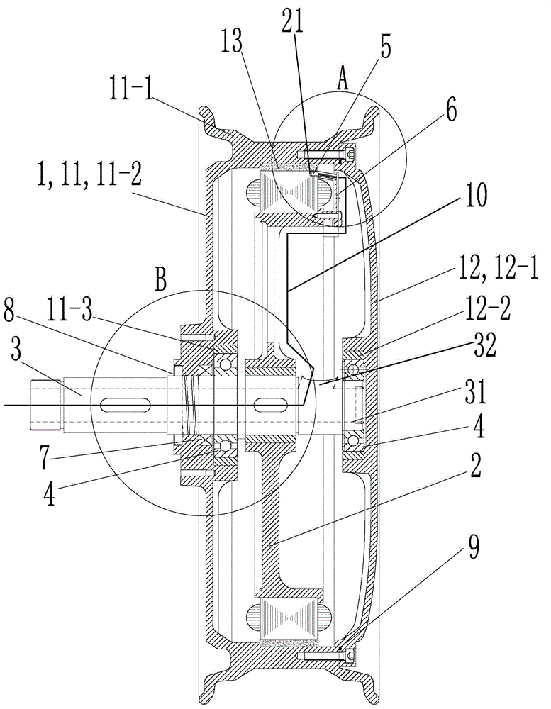
[0002] At present, the driving motor of electric vehicles usually adopts a single-shaft hub-type brushless DC motor. The existing hub-type motors mainly adopt two structures. One is the traditional structure, that is, the rim and the spokes on both sides are split structures. Although the tubeless tire can be installed, the assembly accuracy is low, the assembly efficiency is low, the structure is unstable, and the maintenance is inconvenient; the other is that the rim is an axial split structure. Hub motors are easy to install and have a stable structure, but tubeless tires cannot be installed because of the poor sealing of the rim; the Hall elements of existing hub motors are usually directly installed on the stator, and the heat generated by the eddy current when the stator is working is easy to make the Hall elements Signal drift or even damage; the stator of the existing wheel hub motor is fixed in the middle of the connecting shaft, the connecting shaft is semi-hollow, and the lead hole is set on the wall of the connecting shaft at the position on the left side of the stator, and the part on the left side of the stator on the connecting shaft It is hollow, but on the right side of the stator, the connecting shaft is solid. The stator needs to be removed to repair the line during maintenance. The maintenance is time-consuming and laborious. Moreover, the weight of the connecting shaft is uneven, and the connecting shaft is easily deformed or even broken.

Method used


Image

  • Single-output-shaft hub-type DC brushless motor
  • Single-output-shaft hub-type DC brushless motor
  • Single-output-shaft hub-type DC brushless motor

Examples


Embodiment 1

[0030] See Figure 1 to Figure 6 , the single-shaft hub-type brushless DC motor of this embodiment is mainly composed of a rotor 1, a stator 2, a connecting shaft 3, a bearing 4, a Hall element 5, a Hall element mounting frame 6, an oil seal 7, a dust-proof ring 8 and O-ring 9 components.

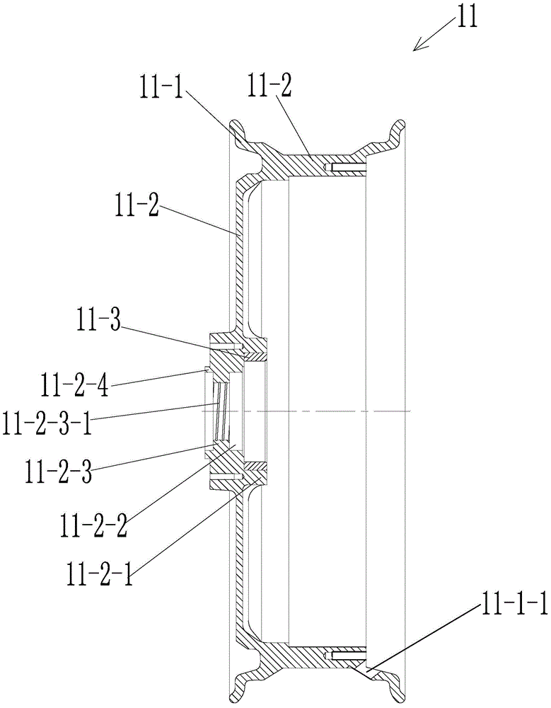
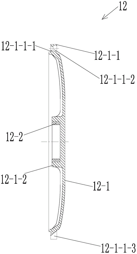
[0031] see figure 2 and image 3 , The rotor 1 is mainly composed of a first housing 11 , a second housing 12 and a magnetic steel 14 .

[0032] The first housing 11 is mainly composed of a rim 11-1, a spoke 11-2 and a bearing sleeve 11-3. The rim 11-1 and the spoke 11-2 are integrally formed, and move from the outside to the center along the radial direction of the first housing 11. These are the rim 11-1 and the spokes 11-2 in turn.

[0033] The rim 11-1 is an irregular ring; the outer inner wall of the rim 11-1 is the installation and connection part of the tubeless tire.

[0034] The spoke 11-2 is disc-shaped, and the spoke is integrally connected with the rim by its outer end sur...


PUM


Abstract

The invention provides a single-output-shaft hub-type DC brushless motor. The single-output-shaft hub-type DC brushless motor includes a rotor, a stator, a connection shaft, bearings, a Hall element, a Hall element mounting frame, an oil seal, a dustproof ring and an O-shaped seal ring. The rotor includes a first shell, a second shell and a steel magnet. The steel magnet is connected with a rim fixedly. The first shell includes the rim, spokes and a bearing sleeve, wherein the rim and the spokes are formed integrally. The Hall element mounting frame is fixed arranged on the stator. The Hall element is fixedly mounted on the Hall mounting frame. The connection shaft is a hollow shaft. According to the invention, the rotor is convenient in assembly, high in precision and good in adaptability. The single-output-shaft hub-type DC brushless motor is good in use safety and reliability and quick and convenient in maintenance and repair.

Description

technical field [0001] The invention relates to the field of motors, in particular to a single-shaft hub type brushless DC motor suitable for application devices such as electric vehicles. Background technique [0002] At present, the driving motor of electric vehicles usually adopts a single-shaft hub-type brushless DC motor. The existing hub-type motors mainly adopt two structures. One is the traditional structure, that is, the rim and the spokes on both sides are split structures. Although the tubeless tire can be installed, the assembly accuracy is low, the assembly efficiency is low, the structure is unstable, and the maintenance is inconvenient; the other is that the rim is an axial split structure. Hub motors are easy to install and have a stable structure, but tubeless tires cannot be installed because of the poor sealing of the rim; the Hall elements of existing hub motors are usually directly installed on the stator, and the heat generated by the eddy current when ...

Claims


Application Information

Patent Timeline
Patent Type & Authority Applications(China)
IPC IPC(8): H02K29/08H02K5/10H02K5/16
Inventor 陈宏兴周聪
Owner CHANGZHOU QIYU ELECTRONICS TECH
Learn More