
Imaging lens

An imaging lens and imaging surface technology, which is applied in the field of imaging lenses, can solve the problems that imaging lenses cannot meet the requirements of miniaturization, light weight, and low temperature effects at the same time, and achieve the effects of shortening the total length of the lens, reducing the impact and effective aberration.

Active Publication Date: 2016-07-13
ETHER +1
View PDF5 Cites 2 Cited by
  • Summary
  • Abstract
  • Description
  • Claims
  • Application Information

AI Technical Summary

Problems solved by technology

[0003] The technical problem to be solved by the present invention is to provide an imaging lens with short total lens length and low temperature effect in view of the defects that the imaging lens in the prior art cannot meet the requirements of miniaturization, light weight, and low temperature effect at the same time , but still has good optical performance, and the lens resolution can also meet the requirements

Method used


Image

  • Imaging lens
  • Imaging lens
  • Imaging lens

Examples


Embodiment Construction

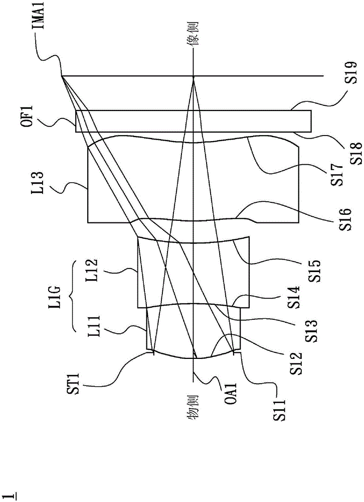
[0028] see figure 1 , figure 1 It is a schematic diagram of lens configuration and optical path according to the first embodiment of the imaging lens of the present invention. The imaging lens 1 sequentially includes an aperture ST1 , a first lens L11 , a second lens L12 , a third lens L13 and an optical filter OF1 along the optical axis OA1 from the object side to the image side. During imaging, the light from the object side is finally imaged on the imaging surface IMA1. The first lens L11 is a biconvex lens with positive refractive power and is made of glass material. The object side S12 is an aspheric surface, and the image side S13 is a spherical surface. The second lens L12 is a biconcave lens with negative refractive power and is made of glass material. The object side S14 is a spherical surface, and the image side S15 is an aspheric surface. The first lens L11 and the second lens L12 are cemented into a cemented lens L1G, and the cemented lens L1G has positive refra...


PUM


Abstract

The invention discloses an imaging lens, which comprises, from an objective side to an image side, a first lens, a second lens, and a third lens along an optical axis. The first lens is the biconvex lens, and is provided with the positive refractive power. The second lens is the biconcave lens, and is provided with the negative refractive power. The third lens is provided with the positive refractive power. The first lens and the second lens are attached together in an adhesive manner to form the adhesive lens, which is provided with the power refractive power. The first lens and the second lens are capable of satisfying the following condition:1,29<=f 12 / f<= 1.34, and f 12 is the combination effective focal length of the first lens and the second lens, and f is the effective focal length of the imaging lens.

Description

technical field [0001] The invention relates to an imaging lens. Background technique [0002] At present, in order to achieve miniaturization and light weight of mobile phone lenses, the lenses used in the lens are all made of plastic materials. However, the temperature effect of a lens using an all-plastic lens is large, and the imaging quality is easily affected by the ambient temperature. Known imaging lenses can no longer meet today's needs, and another imaging lens with a new structure is needed to meet the requirements of miniaturization, light weight, and low temperature effect at the same time. Contents of the invention [0003] The technical problem to be solved by the present invention is to provide an imaging lens with short total lens length and low temperature effect in view of the defects that the imaging lens in the prior art cannot meet the requirements of miniaturization, light weight, and low temperature effect at the same time , but still has good opt...

Claims


Application Information

Patent Timeline
IPC IPC(8): G02B13/00G02B13/18G02B1/00
CPCG02B1/00G02B13/0035G02B13/006
Inventor 詹哲泓
Owner ETHER
Learn More