Air channel assembly of air conditioner, air conditioner, and control method of air conditioner
A technology for air duct components and air conditioners, applied in heating and ventilation control systems, noise suppression, air flow control components, etc., can solve the problems of not being able to meet the differentiated needs of different groups of people, small adjustment angles, unfavorable installation, etc., and achieve improvement Comfort, increasing air volume and air supply distance, increasing the effect of air volume and air supply distance
- Summary
- Abstract
- Description
- Claims
- Application Information
AI Technical Summary
Problems solved by technology
Method used
Image
Examples
Embodiment 1
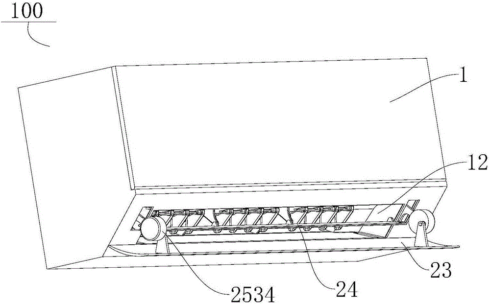
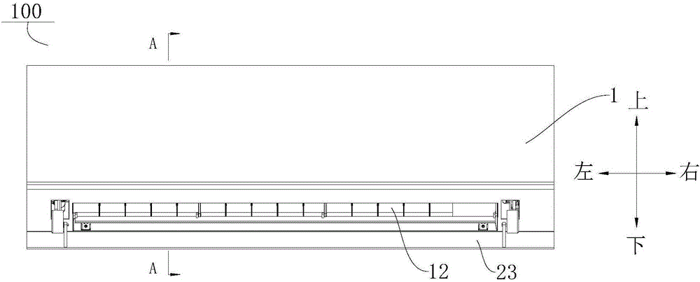
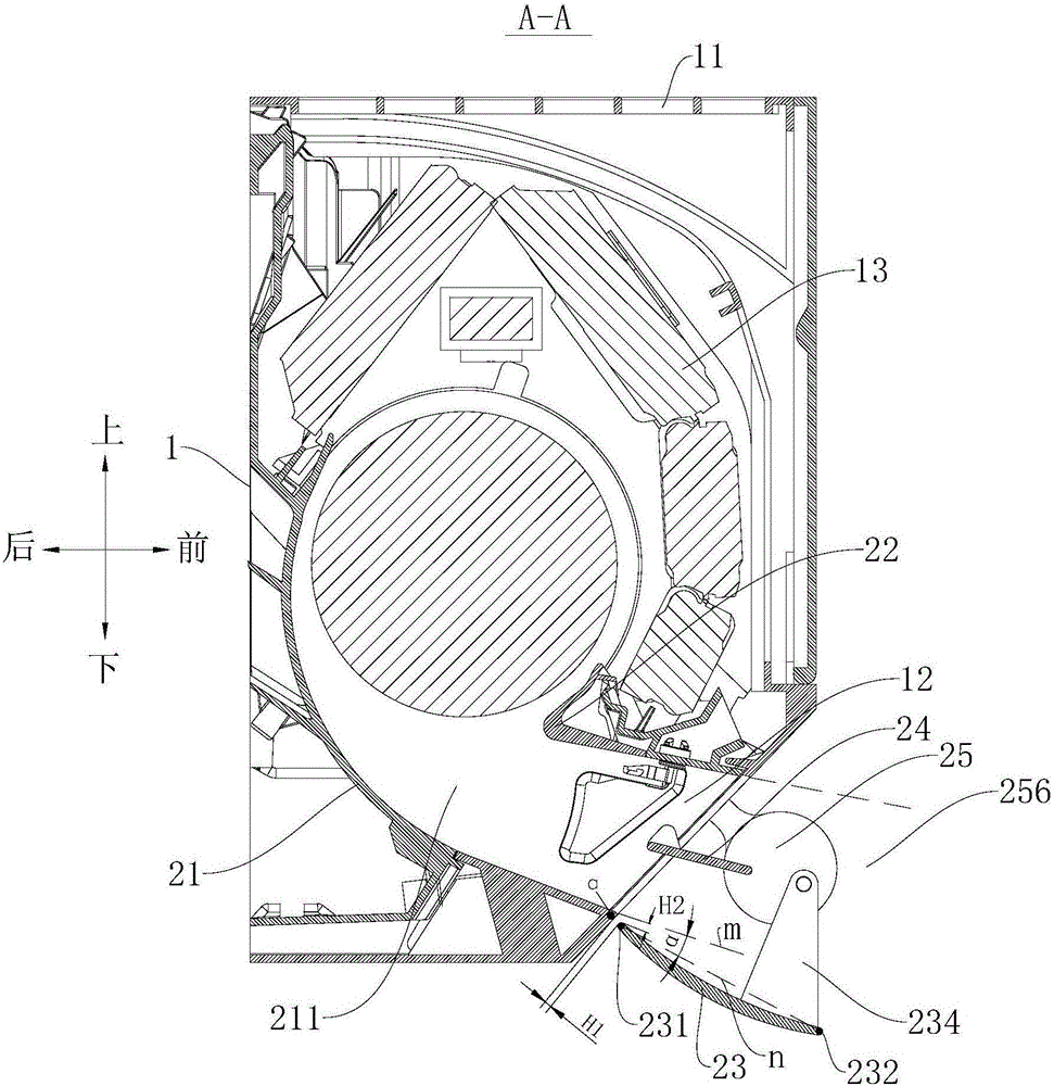
[0163] Such as Figure 1-Figure 15 As shown, the air conditioner 100 according to the embodiment of the present invention includes a housing 1 and an air duct assembly. The housing 1 has an air inlet 11 and an air outlet 12. The air duct assembly is arranged in the housing 1. The air outlet 12 of the air duct assembly is connected to the The shell 1 communicates with the outside, and the heat exchanger 13 is arranged adjacent to the air inlet of the air duct assembly. The air in the room can enter the housing 1 through the air inlet 11 on the housing 1 and perform heat exchange treatment with the heat exchanger 13. After the heat exchange treatment, the air enters the air duct assembly through the air inlet 11 of the air duct assembly, and Exhausted through the air outlet 12 of the air duct assembly.
[0164] Such as image 3 and Figure 13 As shown, the air duct assembly includes a volute 21 , a volute tongue 22 , an air deflector 23 and a drive assembly 25 . The volute t...
Embodiment 2
[0176] Such as Figure 16-Figure 44 As shown, the structure of this embodiment is substantially the same as that of Embodiment 1, and the same components use the same reference numerals. The only difference is that the air outlet area 256 is divided into a first air outlet area 2561 close to the volute tongue 22 and a second air outlet area 2562 close to the volute 21. There is a first predetermined position in the first air outlet area 2561, and a second air outlet area 2562. The wind outlet area 2562 has a second predetermined position. The driving assembly 25 drives the air guide plate 23 to move in the first air outlet area 2561 and the second air outlet area 2562. The air guide plate 23 is rotatably connected with the drive assembly 25. When the rotation axis of the air guide plate 23 is located at the first air outlet area At the first predetermined position in the wind area 2561, the wind deflector 23 opens the air outlet 12, and the wind deflector 23 has a first state...
Embodiment 3
[0184] Such as Figure 45-71 As shown, the structure of the present embodiment is substantially the same as that of the second embodiment, wherein the same components use the same reference numerals, and the only difference lies in the structure of the driving assembly 25 .
[0185] Such as Figure 60-70 As shown, the driving assembly 25 in this embodiment includes a box body 251 , a driving gear 2514 and a connecting rod body 2531 .
[0186] Such as Figure 69 and Figure 70 As shown, the box body 251 is formed into a quadrangular shape and one of the corners is excessively rounded. The box body 251 includes a main body with one side open and a box cover 2512 for closing the main body. The main body and the box cover 2512 are connected by threaded fasteners , The box cover 2512 and the main body define an accommodation space. The outer wall of the box cover 2512 is provided with a first driving motor 2513, the first driving motor 2513 is connected with the box cover 2512 ...
PUM
 Abstract
Description
Claims
Application Information
 - R&D Engineer
- R&D Manager
- IP Professional
- Industry Leading Data Capabilities
- Powerful AI technology
- Patent DNA Extraction
Browse by: Latest US Patents, China's latest patents, Technical Efficacy Thesaurus, Application Domain, Technology Topic, Popular Technical Reports.
© 2024 PatSnap. All rights reserved.Legal|Privacy policy|Modern Slavery Act Transparency Statement|Sitemap|About US| Contact US: help@patsnap.com


