Iron mold power rollgang device

A technology of conveying rollers and iron molds, which is applied in the direction of conveyors, conveyor objects, transportation and packaging, etc., can solve the problems of not realizing the power transmission of iron molds, the inability to realize accurate positioning of iron molds, etc., and achieve the reduction of labor force and occupancy Less space and longer service life

Inactive Publication Date: 2016-07-13
浙江省机电设计研究院有限公司
View PDF6 Cites 4 Cited by
  • Summary
  • Abstract
  • Description
  • Claims
  • Application Information

AI Technical Summary

Problems solved by technology

Although this patent can achieve the purpose of reducing the complexity of the iron mold sand-covered casting production line control system and enhancing its adaptability, as well as improving the settings in the production line to optimize the iron mold sand-coated casting process, it does not realize the iron mold power transmission and cannot realize the iron mold sand-coated casting process. The precise positioning of the type, so it still has the above defects

Method used


Image

  • Iron mold power rollgang device
  • Iron mold power rollgang device
  • Iron mold power rollgang device

Examples


Embodiment Construction

[0020] The present invention will be further described in detail below in conjunction with the accompanying drawings and examples. The following examples are explanations of the present invention and the present invention is not limited to the following examples.

[0021] Example.

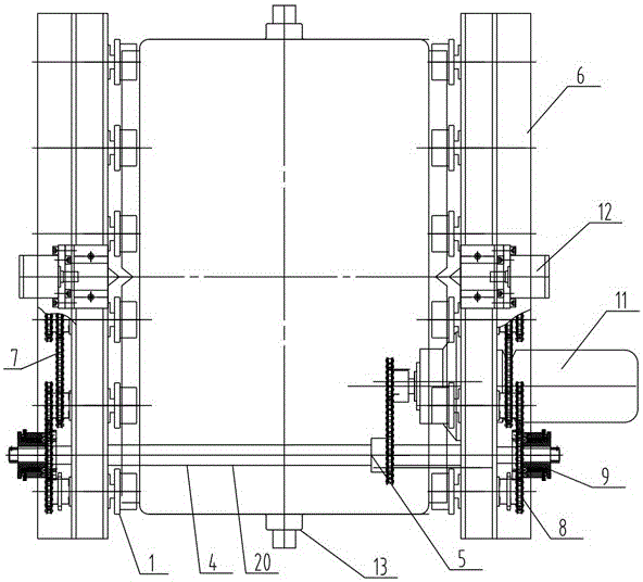
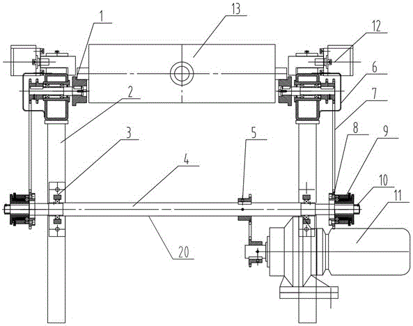
[0022] see Figure 1 to Figure 3 , there are two roller mechanisms 1 in this embodiment, the roller mechanism 1 is installed on the roller frame 2, the motor 11 is fixed on the roller frame 2, the transmission mechanism 20 includes a bearing seat 3, a drive shaft 4, a chain Wheel 5, chain cover 6, chain 7, clutch sprocket 8 and clutch 9, clutch sprocket 8 is fixed on clutch 9, drive shaft 4 is fixed on roller frame 2 through bearing seat 3, drive shaft 4 passes sprocket 5 It is connected with the chain 7 and the motor 11, the outside of the chain 7 is provided with a chain cover 6, and the positioning and clamping mechanism 12 is fixed on the roller frame 2.

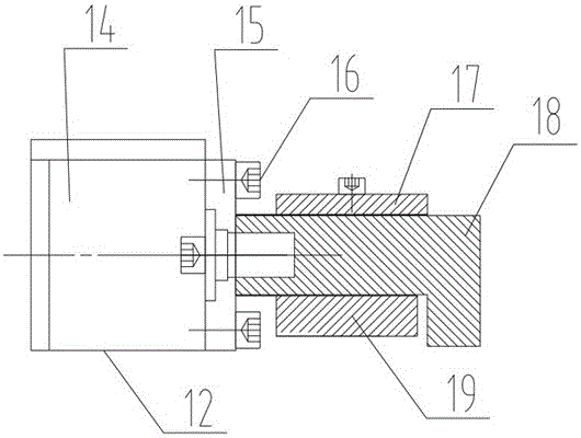
[0023] The positioning and clamping ...


PUM


Abstract

The invention relates to an iron mold power rollgang device, and belongs to the field of sand-lined iron mold casting equipment.The iron mold power rollgang device comprises a rollgang frame, a motor, a plurality of roll mechanisms, a positioning and clamping mechanism and a transmission mechanism.The roll mechanisms are installed on the rollgang frame.The motor is fixed to the rollgang frame.The transmission mechanism comprises a bearing pedestal, a driving shaft, a chain wheel, a chain, a clutch chain wheel and a clutch, the clutch chain wheel is fixed to the clutch, and the driving shaft is fixed to the rollgang frame through the bearing pedestal and is connected with the motor through the chain wheel and the chain.The positioning and clamping mechanism is fixed to the rollgang frame.The iron mold power rollgang device is simple and reasonable in structure, high in production efficiency and small in occupied space, the problems that iron molds on a sand-lined iron mold production line are difficult to convey, and iron molds and rolls are seriously abraded are solved, and accurate positioning is achieved.

Description

technical field [0001] The invention relates to a roller table device, in particular to an iron mold power conveying roller table device for realizing precise positioning, which belongs to the field of iron mold sand-covered casting equipment. Background technique [0002] In recent years, with the continuous increase of labor costs, users have higher and higher requirements for the mechanization of iron mold sand-coated production lines. However, the mechanization of iron mold sand-coated production lines is relatively low at present, especially for iron molds on the production line. The transportation and positioning of the vehicle has always been a difficult problem to solve. [0003] The iron molds of sand-covered casting are divided into upper iron molds and lower iron molds. When the upper and lower iron molds are conveyed on the production line, precise positioning is required, such as: mold clamping with the model during sand shooting molding; upper and lower iron m...

Claims


Application Information

Patent Timeline
Patent Type & Authority Applications(China)
IPC IPC(8): B65G47/88
CPCB65G47/8861B65G2205/04
Inventor 夏小江黄列群潘东杰沈永华高强马益诚应浩刘同帮洪华泽
Owner 浙江省机电设计研究院有限公司
Why Eureka
Try Eureka