Electronic cam control device and electronic cam curve generation method thereof

A technology of electronic cam and control device, applied in the direction of electrical program control, program control, general control system, etc., can solve the problems of machine damage, inconvenient use, etc., and achieve the effect of convenient use

Active Publication Date: 2016-07-06
新代科技(苏州)有限公司
View PDF4 Cites 12 Cited by
  • Summary
  • Abstract
  • Description
  • Claims
  • Application Information

AI Technical Summary

Problems solved by technology

However, this method can only limit the speed and acceleration of the initial point and the end point, and does not limit the speed and acceleration in the process. There may be a large speed and acceleration in the process, which may cause damage to the machine; 4) the existing electronic cam curve The generation method algorithm requires a lot of parameters for each point, such as the point position, speed, acceleration and deceleration interval time, and acceleration interval time, which is not convenient to use

Method used


Image

  • Electronic cam control device and electronic cam curve generation method thereof
  • Electronic cam control device and electronic cam curve generation method thereof
  • Electronic cam control device and electronic cam curve generation method thereof

Examples


Embodiment Construction

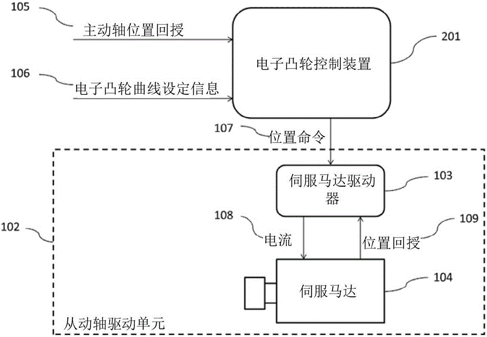
[0035] like figure 1 As shown, the electronic cam control device system, the electronic cam control device 201 receives the master shaft position feedback 105 and the electronic cam curve setting information 106, and after generating the electronic cam curve, sends the position command 107 to the driven shaft drive unit 102. The servo motor driver 103 , the servo motor driver 103 converts the position command 107 into a current 108 and outputs it to the servo motor 104 , and the servo motor 104 transmits the position feedback 109 to the servo motor driver 103 for action, so as to achieve the generation of the electronic cam control device 201 The electronic cam curve movement trajectory.

[0036] like figure 2As shown, the electronic cam control device 201 includes an information reading unit 202, which reads the specific point position and related parameters set by the user from the electronic cam curve setting file 210; an electronic cam curve generating unit 203, accordin...


PUM


Abstract

The invention discloses an electronic cam control device and an electronic cam curve generation method thereof. The device comprises an information reading unit used for reading and analyzing a driven shaft position setting file; an electronic cam curve generation unit used for generating an electronic cam curve according to limiting conditions set by a user; an electronic cam curve memory unit used for storing the generated electronic cam curve; a position command generation unit used for referring to position feedback of a driving shaft and converting a stroke plan of the electronic cam curve into a position command; and a command output unit used for outputting the position command to a driven shaft driving unit which acts according to the received position command. In a stoke planning process, a solver meeting conditions is selected according to the limiting conditions and a solving result of the last time until a solution meeting the limiting conditions is found; and in the solving process, the speed, acceleration, accelerated acceleration and the like in the process are considered, and a machine bench protection function is achieved.

Description

technical field [0001] The invention relates to an electronic cam control device and an electronic cam curve generation method, in particular to an electronic cam control device and an electronic cam curve generation method for generating an electronic cam curve for stroke planning. Background technique [0002] The electronic cam control device can set an electronic cam curve, and then control the servo motor through the servo system, the purpose is to make the position of the driven shaft correspond to the position of the driving shaft to satisfy the corresponding relationship set by the electronic cam curve. Because the electronic cam curve is more flexible and convenient to use, it has gradually been used to replace the traditional mechanical cam. It can be used by setting a new electronic cam curve through software. When the electronic cam curve is generated, a number of specific points will be specified first, these specific points represent the corresponding relation...

Claims


Application Information

Patent Timeline
Patent Type & Authority Applications(China)
IPC IPC(8): G05B19/06
CPCG05B19/063
Inventor 简文昱严举楼王亭谕
Owner 新代科技(苏州)有限公司
Why Eureka
Try Eureka