
Magnetic induction pulse water meter

A magnetic induction and water meter technology, applied to the volume/mass flow generated by electromagnetic effects, the application of electromagnetic flowmeters to detect fluid flow, instruments, etc., can solve the problems of increased management costs, limited measurement accuracy, and low measurement accuracy, and reduce labor. The effect of low cost, low manufacturing cost and high measurement accuracy

Inactive Publication Date: 2016-06-29
福水智联技术有限公司
View PDF10 Cites 9 Cited by
  • Summary
  • Abstract
  • Description
  • Claims
  • Application Information

AI Technical Summary

Problems solved by technology

[0002] More than 90% of the water meters used in daily life are mechanical meters. The traditional water meters have the following defects: 1. The measurement accuracy is limited. When the water flow is small, the leakage loss is large and it is difficult to measure accurately; 2. The measurement accuracy is low and the manufacturing cost is high; 3 .Using manual meter reading increases management costs and makes it difficult to monitor when a fault occurs

Method used


Image

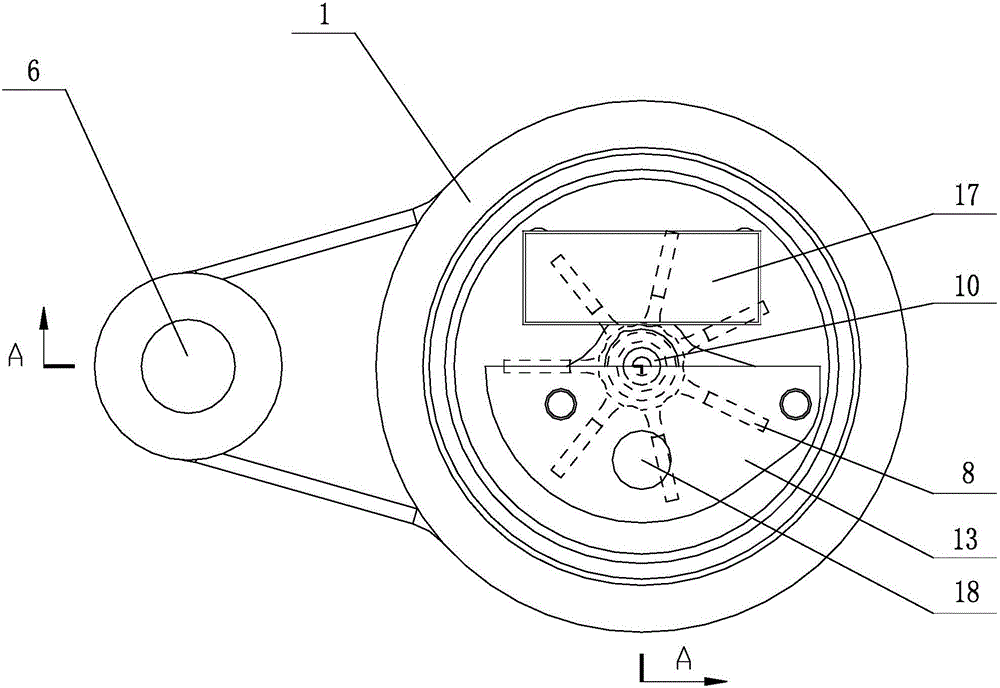
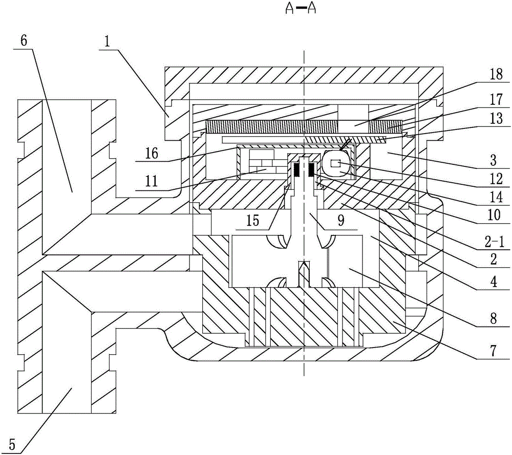
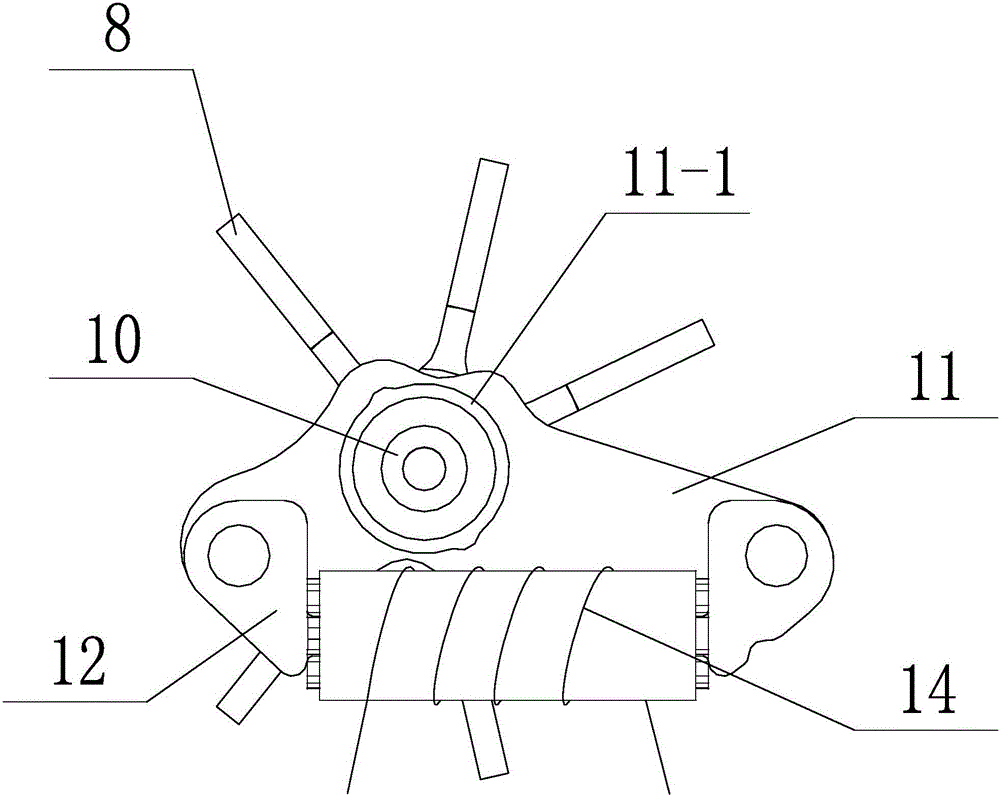
  • Magnetic induction pulse water meter
  • Magnetic induction pulse water meter
  • Magnetic induction pulse water meter

Examples


Embodiment Construction

[0023] The content of the present invention will be described in detail below in conjunction with the accompanying drawings and specific embodiments of the description:

[0024] Such as figure 1 - Figure 6 As shown, a magnetic induction pulse water meter provided by the present invention includes a water meter body 1, and a cavity is provided in the water meter body 1. It is characterized in that: an inner shell base 2 is arranged in the middle of the cavity, and the inner shell base 2 The cavity is divided into an upper cavity 3 above it and a lower cavity 4 below it, the bottom of the lower cavity 4 is provided with a water inlet 5, and the top of the lower cavity 4 is provided with a water outlet 6, so The lower cavity 4 is provided with an impeller base 7, the impeller base 7 is rotatably connected with an impeller 8, the impeller 8 is fixed with an impeller shaft 9, and the inner shell base 2 is provided with an impeller shaft 9 for avoidance. The avoidance hole 2-1, t...


PUM


Abstract

The invention relates to a magnetic induction pulse water meter. The magnetic induction pulse water meter comprises a water meter body and a cavity, wherein an inner shell base is arranged in the cavity and divides the cavity into an upper cavity and a lower cavity, a water inlet is formed at the upper part of the lower cavity and a water outlet is formed at the lower part of the lower cavity, an impeller base is arranged in the lower cavity, an impeller is rotationally connected on the impeller base, an impeller shaft is fixedly arranged on the impeller, an avoidance hole is formed on the inner shell base, the upper end of the impeller shaft penetrates through the avoidance hole to be exposed in the upper cavity, and magnetic steel is arranged at the upper end of the impeller shaft. The water meter also comprises a high magnetic conductive stator piece, a coil holder iron core and a circuit board, wherein a magnetic pole cavity is formed on the high magnetic conductive stator piece, the magnetic steel is positioned in the magnetic pole cavity, a coil is wound on the coil holder iron core, and the circuit board is connected with the coil. According to the water meter, the impeller shaft drives the magnetic steel to rotate to make the coil generate a pulse signal and convert the pulse signal into a water flow rate information, the measurement precision is high, the measurement accuracy is high when the water flow rate is low, and the leakage is low; and the water meter has the advantages of low manufacture cost, high precision, convenience in installation and the like.

Description

technical field [0001] The invention relates to a water meter, in particular to a magnetic induction pulse water meter. Background technique [0002] More than 90% of the water meters used in daily life are mechanical meters. The traditional water meters have the following defects: 1. The measurement accuracy is limited. When the water flow is small, the leakage loss is large and it is difficult to measure accurately; 2. The measurement accuracy is low and the manufacturing cost is high; 3 .Using manual meter reading increases management costs and makes monitoring difficult when faults occur. Contents of the invention [0003] The purpose of the present invention is to overcome the above disadvantages and provide a magnetic induction pulse water meter, which drives the magnet steel to rotate through the impeller shaft to generate a pulse signal on the coil, and converts the pulse signal into water flow information, so that the measurement accuracy is high and in the water ...

Claims


Application Information

Patent Timeline
Patent Type & Authority Applications(China)
IPC IPC(8): G01F1/58G01F15/00
CPCG01F1/58G01F1/586G01F1/588G01F15/00
Inventor 黄训松张惠益范耀荣高捷苏光源黄朝峰连峰胡淋清康利珍蒋淼
Owner 福水智联技术有限公司
Learn More