Wired electric appliance with binder clip

A technology of wired electrical appliances and long tail clips, which is applied in the field of limited electrical structure design, and can solve the problems of being tangled into a mess, cable ties, cable and rubber bands are easy to lose, and hinder the use of the next ligation.

Active Publication Date: 2016-06-29
乐清市川嘉电气科技有限公司
View PDF7 Cites 1 Cited by
  • Summary
  • Abstract
  • Description
  • Claims
  • Application Information

AI Technical Summary

Problems solved by technology

[0002]Existing wired devices all have long cables, which are easily tangled into a mess when carried and stored, which is quite inconvenient to use
When these electrical appliances with cables leave the factory, their single cables are repeatedly folded to form a bundle of cables, and then tied on the bundle of cables with cable ties, cables or rubber bands. Disassemble the cable ties, cables or rubber bands, so the cable ties, cables and rubber bands are easily lost, which hinders the use of the next ligation
[0003] The existing long tail clamp includes a clamping piece and two clamping handles; the clamping piece includes two splints made in one piece, and the two sides of the end plate of each splint are bent and rolled back toward the outside of the splint to form two pin holes; Each clamping handle is made of steel wire, and each clamping handle includes two load-bearing parts. The two ends of the two load-bearing parts are bent to form two pins, and each pin is inserted in a corresponding pin hole; The structure allows the long tail clip to be clamped on a single cable of a wired device by using its two splints, but it still cannot be used to tidy up the cable, so there is still room for improvement in its structure

Method used


Image

  • Wired electric appliance with binder clip
  • Wired electric appliance with binder clip
  • Wired electric appliance with binder clip

Examples


Embodiment Construction

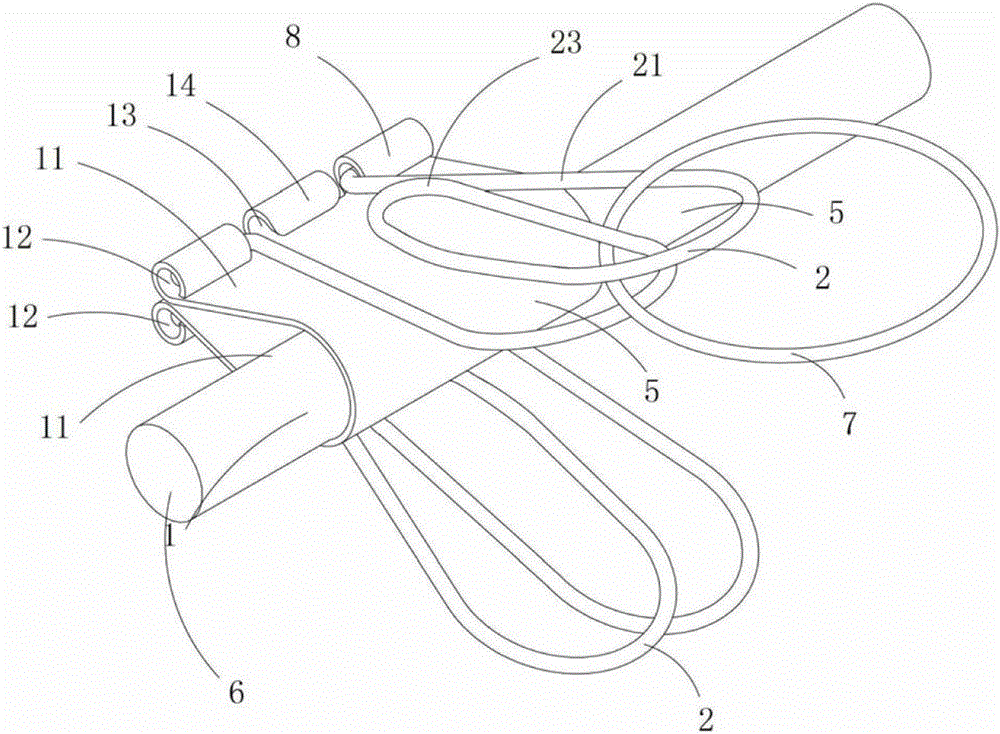
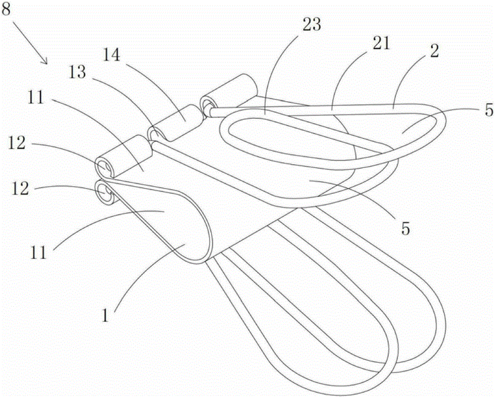
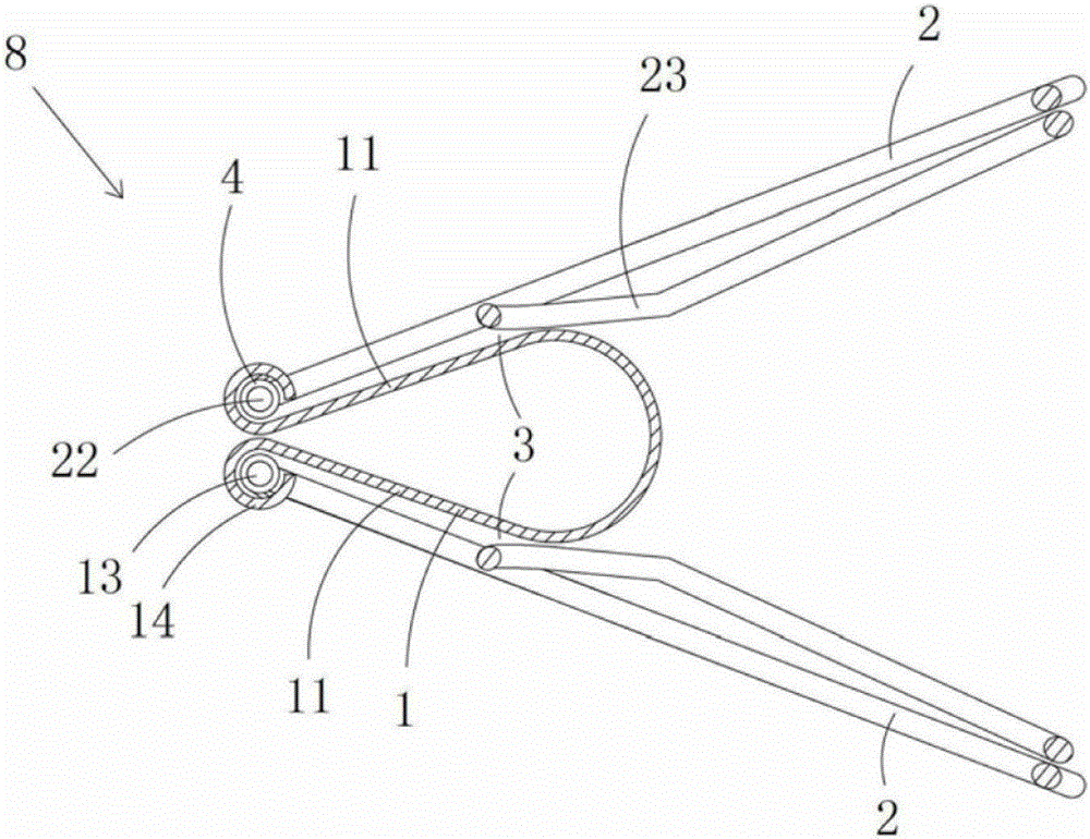
[0010] Figure 1 to Figure 3 A specific embodiment of the invention is shown in which, figure 1 It is a schematic diagram of a three-dimensional structure of the present invention; figure 2 Yes figure 1 A schematic diagram of a three-dimensional structure of the long tail clip in the shown wired appliance; image 3 Yes figure 2 A cutaway view of the long tail clip shown.

[0011] This embodiment is a wired electrical appliance with a long tail clip, see Figure 1 to Figure 3 As shown, it includes a cable 6 connected to the finite electrical body and a long tail clip 8 arranged on the cable. The long tail clip includes a clamping piece 1 and two clamping handles 2; the clamping piece includes two integrally made Plywood 11, the two sides of each plywood end plate are bent and rolled back toward the outside of the plywood to form two pin holes 12; The two ends of the part are bent to form two pins 22, and each pin is inserted in a corresponding pin hole; the middle part ...


PUM


Abstract

The invention discloses a wired electric appliance with a binder clip. The wired electric appliance with the binder clip comprises a cable connected with a wired electric appliance body, and the binder clip. The binder clip comprises a clamping-connecting piece and two clamping handles, the clamping-connecting piece comprises two clamping plates, and the tail ends of each clamping plate are bent and rewound to form two pin holes; each clamping handle comprises two bearing portions, the two tail ends of the two bearing portions of each clamping handle are bent to form two pin columns, and the pin columns are inserted into the corresponding pin holes; the middle of each clamping handle is wound to form a limiting portion, a torsional spring is arranged in each pin hole, and the middles of the limiting portions are made to abut against the outer walls of the clamping plates under the reset elastic effect of the torsional springs; each limiting portion, the corresponding bearing portions and the outer wall of the corresponding clamping plate are combined to form a sleeve hole; the binder clip is connected with an elastic binding ring through the sleeve holes and clamped on the single cable through the clamping-connecting piece; and the binder clip can be arranged on a bundled cable through the elastic binding ring in a sleeving mode. The wired electric appliance with the binder clip has the advantages of being convenient to use and binding the cable in order.

Description

technical field [0001] The invention belongs to the technical field of structural design of limited electrical appliances, and in particular relates to a wired electrical appliance with a long tail clip. Background technique [0002] Existing wired devices all have relatively long cables, which are easily tangled into a mess when being carried and stored, which is quite inconvenient to use. When these electrical appliances with cables leave the factory, their single cables are repeatedly folded to form a bundle of cables, and then tied on the bundle of cables with cable ties, cables or rubber bands. Disassemble the cable tie, cable or rubber band, so the cable tie, cable and rubber band are easily lost, which hinders the next ligation. [0003] The existing long tail clip includes a clamping piece and two clamping handles; the clamping piece includes two splints made in one piece, and the two sides of the end plate body of each splint are bent and rolled back toward the out...

Claims


Application Information

Patent Timeline
IPC IPC(8): B65D85/04
CPCB65D85/04
Inventor 胡妍
Owner 乐清市川嘉电气科技有限公司
Why Eureka
Try Eureka