
A wheel with adjustable comfort

A technology of comfort and wheels, applied in tire measurement, vehicle parts, tire parts, etc., can solve problems such as hidden safety hazards and existing safety hazards, and achieve the effect of changing comfort, simple structure, and good practical effect

Inactive Publication Date: 2018-10-30
徐州百芈商贸有限公司
View PDF7 Cites 0 Cited by
  • Summary
  • Abstract
  • Description
  • Claims
  • Application Information

AI Technical Summary

Problems solved by technology

[0002] In the daily driving process, the tire pressure is a very important parameter, which can determine the comfort and safety of the car. At present, whether the tire pressure of low-end cars is qualified depends entirely on the driver's experience or targeted testing. There are certain potential safety hazards; in high-end cars, tire pressure data is often reflected on the center console of the car in real time by adding tire pressure detection, so that the driver can understand
However, when the tire pressure is insufficient, even if the driver of a high-end car knows that the tire pressure is insufficient through the center console and goes to the auto repair shop to inflate, there will still be a journey with insufficient tire pressure in the middle, and there are still potential safety hazards, let alone no Low-end cars with tire pressure detection; in addition, for the same tire, there is a range of standard tire pressure. Within the range of standard tire pressure, more or less air will have a certain impact on the driving performance of the car. If it can be within the standard range of tire pressure If it is adjusted in real time according to the driver's requirements, the quality of the car will be improved to a higher level.

Method used


Image

  • A wheel with adjustable comfort
  • A wheel with adjustable comfort
  • A wheel with adjustable comfort

Examples


Embodiment Construction

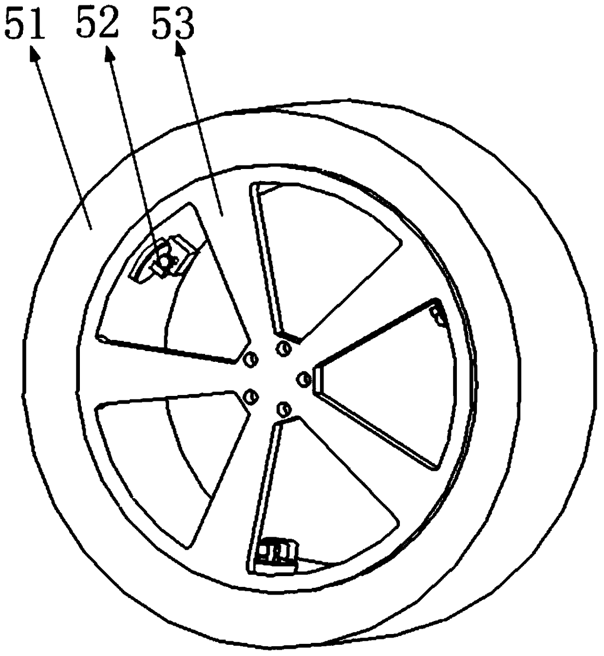
[0018] Such as figure 1 As shown, it includes a tire, a tire pressure regulating mechanism, and a wheel hub, wherein the tire is installed on the outer edge of the wheel hub, and the tire pressure regulating mechanism is installed on the inner edge of the wheel hub.

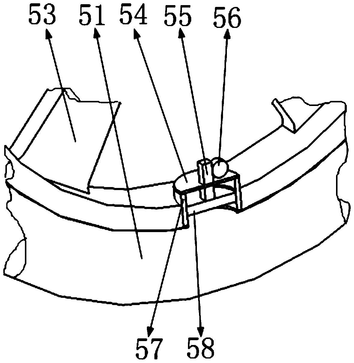
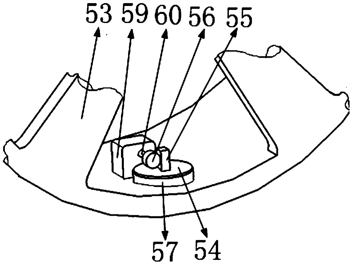
[0019] Such as figure 2 , 3 As shown, the above-mentioned tire pressure regulating mechanism includes a tire pressure regulating mechanism cover plate, a tire pressure regulating mechanism reciprocating rack, a tire pressure regulating mechanism gear, a tire pressure regulating mechanism side wall, a tire pressure regulating mechanism piston, a tire pressure regulating mechanism power, a tire The power shaft of the pressure adjustment mechanism, such as figure 2 As shown, the side wall of the tire pressure adjustment mechanism is installed on the wheel hub, and one end communicates with the inside of the tire, and the other end communicates with the atmosphere; the cover plate of the tire pressure adjustment ...


PUM


Abstract

The invention belongs to the technical field of wheels and particularly relates to a wheel with an adjustable comfort degree. The wheel comprises tire pressure adjusting mechanisms, a hub, a tire, a tire pressure adjusting mechanism cover plate, a tire pressure adjusting mechanism gear, a tire pressure adjusting mechanism side wall, tire pressure adjusting mechanism pistons, a tire pressure adjusting mechanism power source and a tire pressure adjusting mechanism power rotary shaft, wherein the three tire pressure adjusting mechanisms are evenly installed on the inner edge face of the hub in the circumferential direction, the pistons are installed in the tire pressure adjusting mechanisms, one end of each piston is communicated with the inside of the tire, the positions, relative to the tire pressure adjusting mechanism side walls, of the pistons in the tire pressure adjusting mechanisms are adjusted so that gas pressure in the tire can be adjusted, and therefore the comfort degree of the tire is changed to a certain extent. Besides, when the tire pressure of the tire is insufficient, the pistons in the tire pressure adjusting mechanisms are adjusted to guarantee that the tire pressure of the tire is within a standard pressure range. The three tire pressure adjusting mechanisms are used for adjusting the tire pressure of the tire, the structure is simple, and a good practical effect is achieved.

Description

Technical field [0001] The invention belongs to the technical field of wheels, in particular to a wheel with adjustable comfort. Background technique [0002] In the daily driving process, the tire pressure is a very important parameter, which can determine the comfort and safety of the car. At present, whether the tire pressure of low-end cars is qualified depends entirely on the driver's experience or targeted testing. There are certain potential safety hazards; in high-end cars, tire pressure data is often reflected on the center console of the car in real time by adding tire pressure detection, so that the driver can understand. However, when the tire pressure is insufficient, even if the driver of a high-end car knows that the tire pressure is insufficient through the center console and goes to the auto repair shop to inflate, there will still be a journey with insufficient tire pressure in the middle, and there are still potential safety hazards, let alone no Low-end ...

Claims


Application Information

Patent Timeline
Patent Type & Authority Patents(China)
IPC IPC(8): B60C23/10
CPCB60C23/10
Inventor 柳超
Owner 徐州百芈商贸有限公司
Learn More