Independent electrically tunable dual-band bandpass filters
A dual-band bandpass and filter technology, applied to waveguide devices, circuits, electrical components, etc., can solve the problems of less than 5% relative bandwidth and narrow filter working bandwidth, and achieve good isolation between passbands and good selection performance, the effect of large return loss
- Summary
- Abstract
- Description
- Claims
- Application Information
AI Technical Summary
Problems solved by technology
Method used
Image
Examples
Embodiment
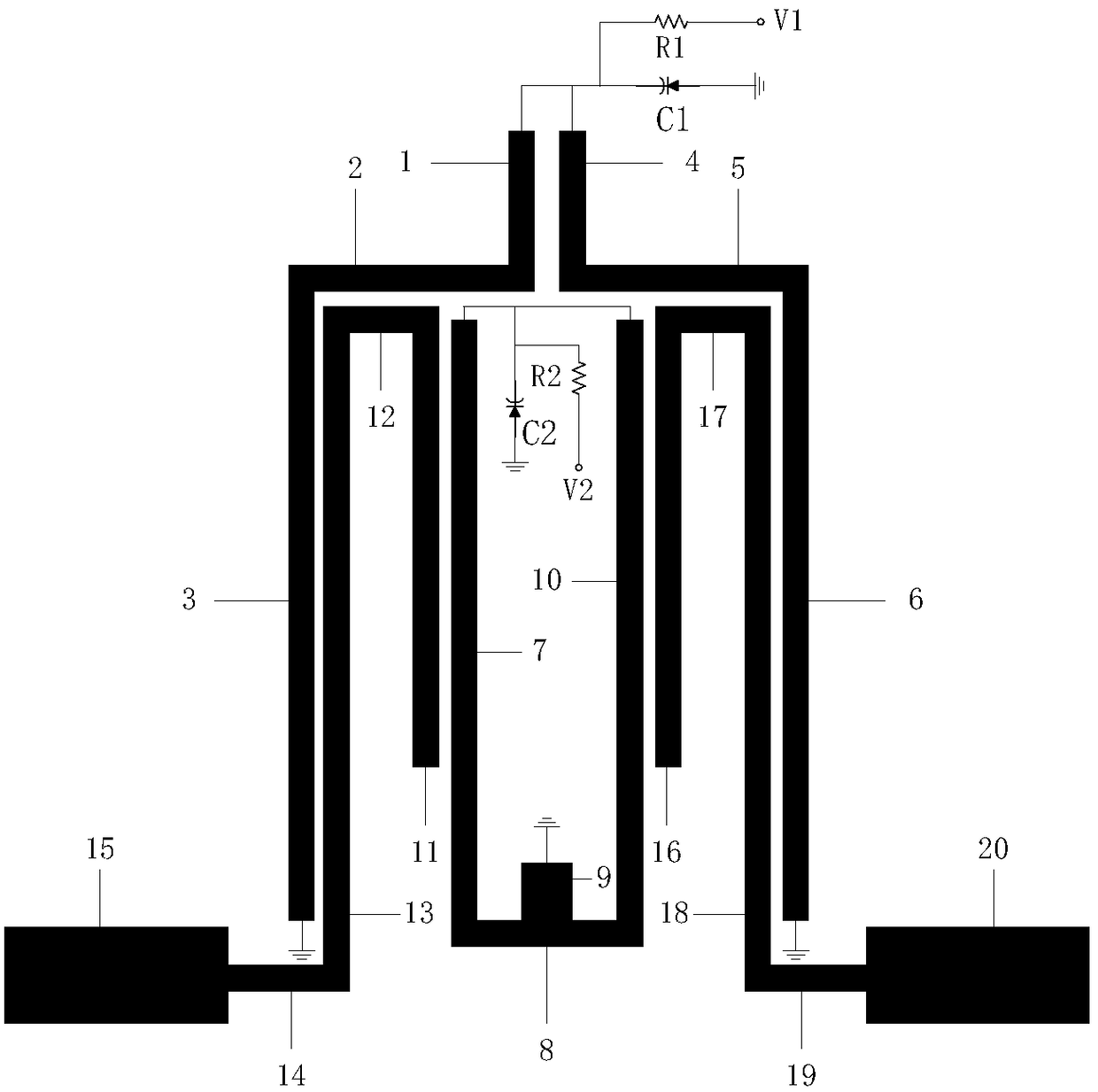
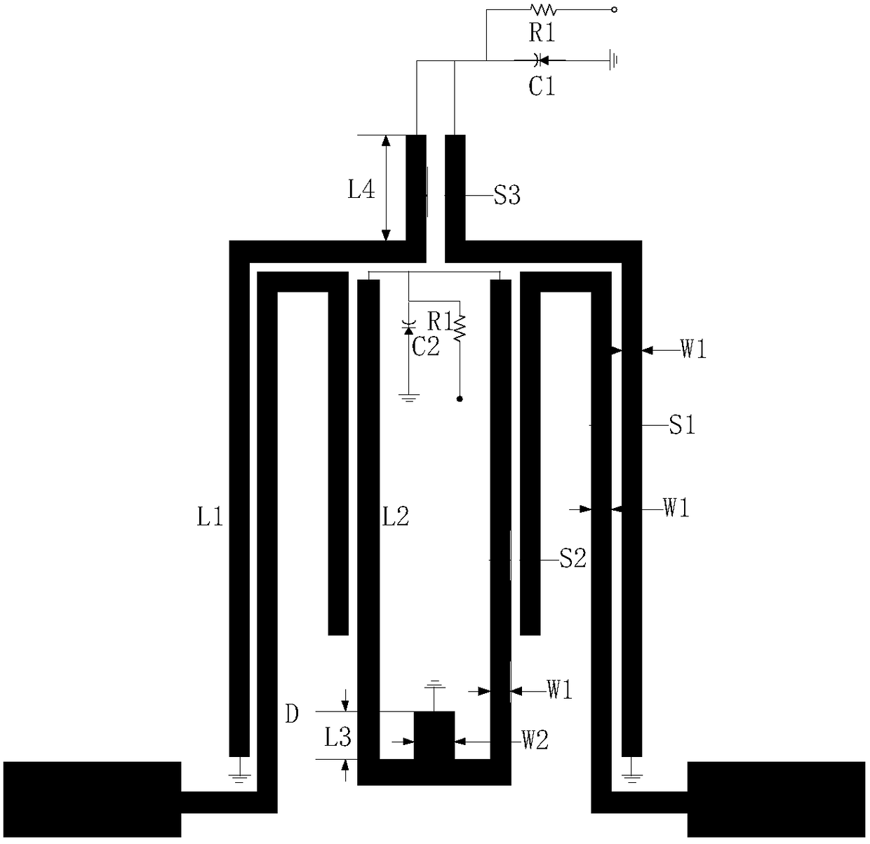
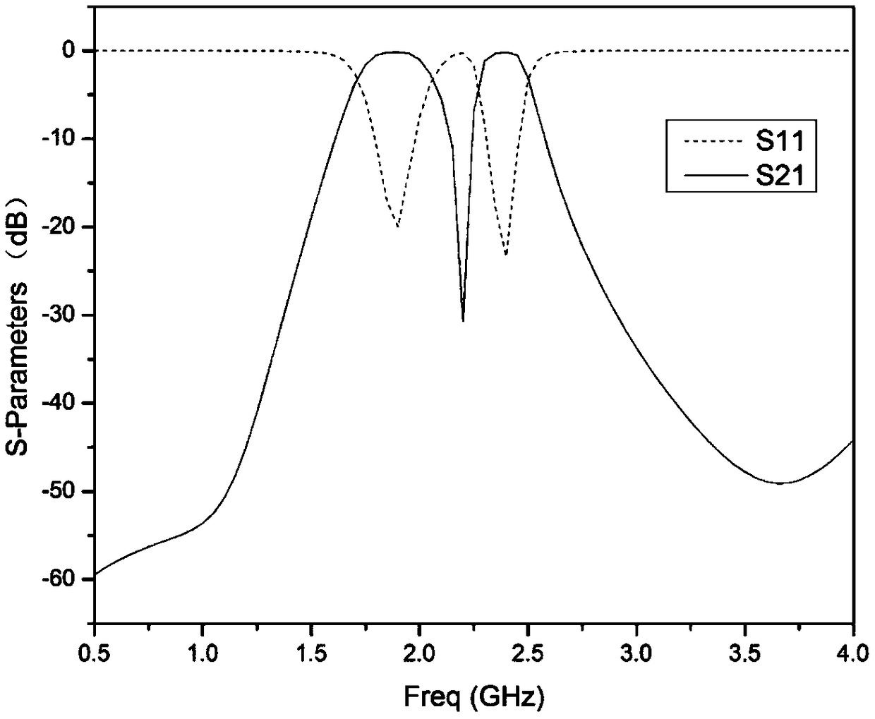
[0028] In this embodiment, the structure of the independent electrically tunable dual-band bandpass filter based on the stub line loaded resonator is as follows figure 1 As shown, the dimensions are as figure 2 shown. The dielectric plate used is Rogers RT / duroid 5880, with a thickness of 0.508 mm, a relative dielectric constant of 2.2, and a loss tangent of 0.0009. The size parameters of each microstrip line of the filter are as follows: W1=0.3mm, W2=0.6mm, S1=0.1mm, S2=0.1mm, S3=0.16mm, L1=28.15mm, L2=22mm, L3=1.5mm, D = 34.5mm. The width of the 50 ohm input and output feeder is 1.54mm, and the area of the microstrip line of the filter is 18.9×26.5mm 2 , the corresponding guide wavelength size is 0.168λ g ×0.235λ g , where λ g is the waveguide wavelength corresponding to the central frequency of the first passband. The length and width of the above microstrip lines are selected to obtain optimal in-band transmission characteristics, out-of-band attenuation characte...
PUM
 Abstract
Description
Claims
Application Information
 - R&D
- Intellectual Property
- Life Sciences
- Materials
- Tech Scout
- Unparalleled Data Quality
- Higher Quality Content
- 60% Fewer Hallucinations
Browse by: Latest US Patents, China's latest patents, Technical Efficacy Thesaurus, Application Domain, Technology Topic, Popular Technical Reports.
© 2025 PatSnap. All rights reserved.Legal|Privacy policy|Modern Slavery Act Transparency Statement|Sitemap|About US| Contact US: help@patsnap.com


