
Automatic numbering device and method for temperature sensors

A temperature sensor and automatic numbering technology, applied in the field of building construction, can solve the problems of low sensitivity of temperature sensor, long time consumption, omission or error of numbering, etc., to improve the work effect and overcome the effect of long time consumption.

Active Publication Date: 2016-06-15
SHANGHAI CONSTRUCTION GROUP +1
View PDF4 Cites 5 Cited by
  • Summary
  • Abstract
  • Description
  • Claims
  • Application Information

AI Technical Summary

Problems solved by technology

[0010] 2) Time-consuming
Since the sensitivity of temperature sensors is generally low, it takes about 10s to 15s to see the value after the temperature change, so hundreds of sensors are numbered sequentially, which takes a long time
[0011] 3) High error rate
The above two methods are still manual operations in essence. In the process of sensor numbering, due to the negligence of the operator, it is easy to cause numbering omissions or errors.

Method used


Image

  • Automatic numbering device and method for temperature sensors
  • Automatic numbering device and method for temperature sensors
  • Automatic numbering device and method for temperature sensors

Examples


Embodiment 1

[0034] Please refer to Figure 1-6 , the first embodiment provides an automatic numbering device for temperature sensors, including

[0035] The power supply circuit 5 provides power supply; the power supply circuit 5 includes a rectification circuit 51 , a filter circuit 52 and a voltage stabilization circuit 53 .

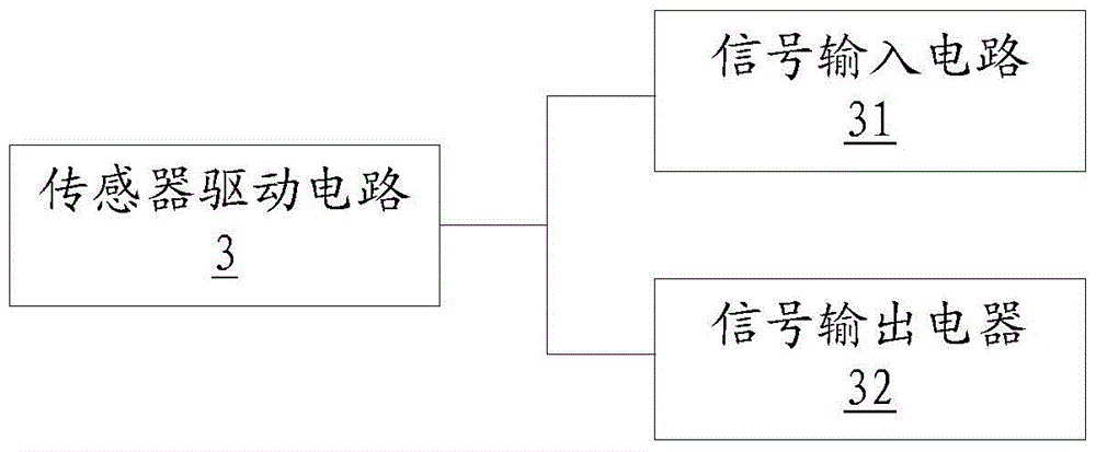
[0036]The sensor drive circuit 3 is used to drive all the temperature sensors of the temperature measurement axis; the sensor drive circuit 3 includes a signal input circuit 31 and a signal output circuit 32; wherein the signal output circuit 32 is used to output the control signal of the data processing circuit 1 To the temperature sensor; wherein the signal input circuit 31 is used to send the temperature signal collected by the temperature sensor to the data processing circuit 1 .

[0037] The display circuit 2 is used to display the current temperature information of the temperature sensor; the display circuit 2 includes a display screen 21, which is used to ...

Embodiment 2

[0041] Please refer to Figure 7 , the second embodiment provides a method for automatic numbering of temperature sensors, comprising the following steps:

[0042] First, integrate the temperature function measured by the temperature sensor at the nth position of the temperature measurement axis for the kth time to obtain the integral function Wherein, k and n are natural numbers greater than 0;

[0043] Second, the integral function of the current temperature of the temperature sensor at the nth position Integral function with last temperature The maximum function of the absolute value of the difference in temperature Compare with the set temperature difference threshold Tc;

[0044] Again, when the maximum function When the temperature value is greater than the temperature difference threshold Tc, the temperature sensor at the nth position is automatically numbered;

[0045] Finally, repeat the above steps until the automatic numbering of all temperature sensors o...


PUM


Abstract

The invention discloses an automatic numbering device and method for temperature sensors. The device comprises a power supply circuit, a sensor drive circuit, a display circuit, an input circuit, and a data processing circuit. The method comprises following steps: performing integration to a temperature function of kth time measurement of a temperature sensor at the nth position on a temperature measurement axis to obtain an integral function of integral Tn<k>, n belongs to (k-1, k); comparing a maximum function: {Maximum value of absolute value of [integral Tn<k>, n belongs to (k-1,k)-integral Tn<k>, n belongs to (k-2, k-1)]}, of absolute values of temperature difference between the current temperature integral function of [integral Tn<k>, n belongs to (k-1, k)] of a sensor at the nth position and the last time temperature integral function of integral Tn<k>, n belongs to (k-2, k-1) with a set temperature difference threshold Tc; when a temperature value of the maximum function: {Maximum value of absolute value of [integral Tn<k>, n belongs to (k-1,k)-integral Tn<k>, n belongs to (k-2, k-1)]}, is larger than the temperature difference threshold Tc, then the temperature sensor at the nth position is automatically numbered; repeating above steps until all the temperature sensors of the temperature measurement axis are automatically finished numbering. The method has small time consumption and high accuracy; by use of the device and method, automatic numbering of temperature sensors can be realized, work efficiency is increased, and the cases of omissions and errors due to artificial numbering are avoided.

Description

technical field [0001] The invention relates to a temperature sensor sorting and numbering device in the technical field of building construction, in particular to a temperature sensor automatic numbering device and method. Background technique [0002] In recent years, with the trend of complex and large-scale building structures, large-volume concrete structures have emerged at home and abroad. In order to ensure that the construction quality of the mass concrete structure meets expectations, real-time monitoring of the concrete temperature distribution during the construction of the structure is required. At present, it is generally used to bury a large number of temperature sensors inside the concrete and collect the sensor measurement data in real time through intelligent acquisition nodes to achieve monitoring purposes. These large number of temperature sensors are distributed on several temperature measuring axes, and the temperature measuring axes are buried in In t...

Claims


Application Information

Patent Timeline
IPC IPC(8): G01K13/00
CPCG01K13/00
Inventor 赵一鸣范志宏严平伍小平李鑫奎周向阳
Owner SHANGHAI CONSTRUCTION GROUP
Learn More