
A method for laying main cables of a flat-stayed cable bridge and the double-layer cable saddle used

A flat-stayed cable bridge and cable saddle technology, applied in bridge construction, bridges, bridge parts, etc., can solve problems such as the limitation of the scope of application of the cable saddle, the large bending strength of the main cable wire, etc., and improve the stability and safety of the bridge. , Improve the scope of application, the effect of simple structure

Active Publication Date: 2017-06-20
CHINA POWER CONSRTUCTION GRP GUIYANG SURVEY & DESIGN INST CO LTD
View PDF5 Cites 0 Cited by
  • Summary
  • Abstract
  • Description
  • Claims
  • Application Information

AI Technical Summary

Problems solved by technology

A single-layer cable saddle is generally composed of a vertical mounting plate, a bottom plate, and a pulley. However, due to the small diameter of the cable-bearing surface of the pulley, it is easy to make the main cable steel wire bear a large bending strength, so the scope of application of the cable saddle is limited.

Method used


Image

  • A method for laying main cables of a flat-stayed cable bridge and the double-layer cable saddle used
  • A method for laying main cables of a flat-stayed cable bridge and the double-layer cable saddle used
  • A method for laying main cables of a flat-stayed cable bridge and the double-layer cable saddle used

Examples


Embodiment

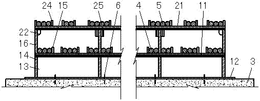
[0028] This example Figure 1-3 As shown, it consists of the lower cable saddle 1 and the upper layer cable saddle 2. The lower layer of cable saddle 1 is fixed on the foundation 3, while the upper layer of cable saddle 2 and the lower layer of cable saddle 1 are clamped. Both the lower cable saddle 1 and the upper layer cable saddle 2 are steel structures. Such as Figure 4-7 As shown, the lower cable saddle 1 includes a lower cable bearing plate 11 , a base plate 12 , a wing plate 13 , a lower partition 14 , a middle partition 15 and a supporting plate 16 . Such as Figure 8-11 As shown, the upper cable saddle 2 includes an upper cable board 21 , a horizontal clamping plate 22 , a vertical clamping plate 23 and an upper partition 24 . The lower cable bearing plate 11 and the upper cable bearing plate 21 are arc-shaped plates along the bridge direction, and are used to support the upper main cable 5 and the lower main cable 4 . An upper partition 24 is arranged above the...


PUM


Abstract

The invention discloses a laying method for a main cable of a flat tension cable bridge and an applied double-layer cable saddle. According to the laying method for the main cable of the flat tension cable bridge and the applied double-layer cable saddle, parts of middle clapboards of an original single-layer cable saddle are heightened to form a lower-layer cable saddle, an upper-layer cable saddle is clamped at the top of the lower-layer cable saddle through transverse clamping plates and a longitudinal clamping plate, and the bottom of the lower-layer cable saddle penetrates through a bottom plate and is fixed to a foundation through bolts. The specific installation sequence comprises that the lower-layer cable saddle is fixed to the foundation through the bolts; a lower-layer main cable is installed on the arc-shaped surface of a lower cable bearing plate of the lower-layer cable saddle; the upper-layer cable saddle is clamped at the top of the lower-layer cable saddle through the transverse clamping plates and the longitudinal clamping plate; and an upper-layer main cable is installed on the arc-shaped surface of an upper cable bearing plate of the upper-layer cable saddle. By means of the novel double-layer laying method for the main cable of the flat tension cable bridge provided by the invention, the application range is greatly widened, and the installation requirements for the main cable are met through the layered structure design of the cable saddle; meanwhile, the folding stress of a steel wire of the main cable is reduced, and the stability and the safety of the bridge are improved; the structure is simple, and installation is convenient.

Description

technical field [0001] The invention relates to a method for laying main cables of a flat-stayed cable bridge and a double-layer cable saddle used, belonging to the technical field of flat-stayed cable bridge structures. Background technique [0002] The flat-stayed cable bridge is a flexible bridge system with the main cable as the stress structure, the bridge deck is directly laid on the main cable, and the line shape of the bridge deck is basically consistent with the line shape of the main cable. The main cable of the flat-stayed cable bridge changes direction through the cable saddle, and then is anchored on the anchorage structure. The main cables of existing flat-stayed cable bridges are all single-layer structures, so the cable saddles are also single-layer cable saddles. A single-layer cable saddle is generally composed of a vertical mounting plate, a bottom plate, and a pulley. However, due to the small diameter of the cable-bearing surface of the pulley, it is ea...

Claims


Application Information

Patent Timeline
Patent Type & Authority Patents(China)
IPC IPC(8): E01D19/14E01D19/16E01D21/00
CPCE01D19/14E01D19/16E01D21/00
Inventor 谢春生
Owner CHINA POWER CONSRTUCTION GRP GUIYANG SURVEY & DESIGN INST CO LTD
Learn More