
Eccentric boosting type slingshot

An eccentric and slingshot technology, which is applied in entertainment, toys, etc., can solve problems such as shaking, unbalanced elastic force of rubber bands, and reduced driving force of rubber bands, and achieve improved shooting accuracy, extended shooting distance, and strong control performance. Effect

Active Publication Date: 2016-06-15
扬州捷兴智能科技有限公司
View PDF5 Cites 1 Cited by
  • Summary
  • Abstract
  • Description
  • Claims
  • Application Information

AI Technical Summary

Problems solved by technology

The power of the slingshot depends on the elastic force and length of the rubber band, but due to the limitation of the human body's arm span, the length of the rubber band cannot be extended indefinitely. The stretched length of the rubber band is proportional to the elastic force. The force is relatively large, often accompanied by shaking, which is not conducive to aiming. After the bullet pocket is released, the driving force of the rubber band on the bullet pocket decreases sharply. These factors are not conducive to accurate shooting.
In addition, the bullet bag is set in the middle of the rubber band. During use, the bow body of the slingshot is required to be perpendicular to the line of sight. Otherwise, it is easy to cause the elastic force of the rubber bands on both sides of the bullet bag to be unbalanced, and the fired projectile deviates from the line of sight. However, the bow of an ordinary slingshot The body and the handle are fixedly connected, it is difficult to keep the bow body perpendicular to the aiming line, and the shooting accuracy is affected

Method used


Image

  • Eccentric boosting type slingshot
  • Eccentric boosting type slingshot
  • Eccentric boosting type slingshot

Examples


Embodiment Construction

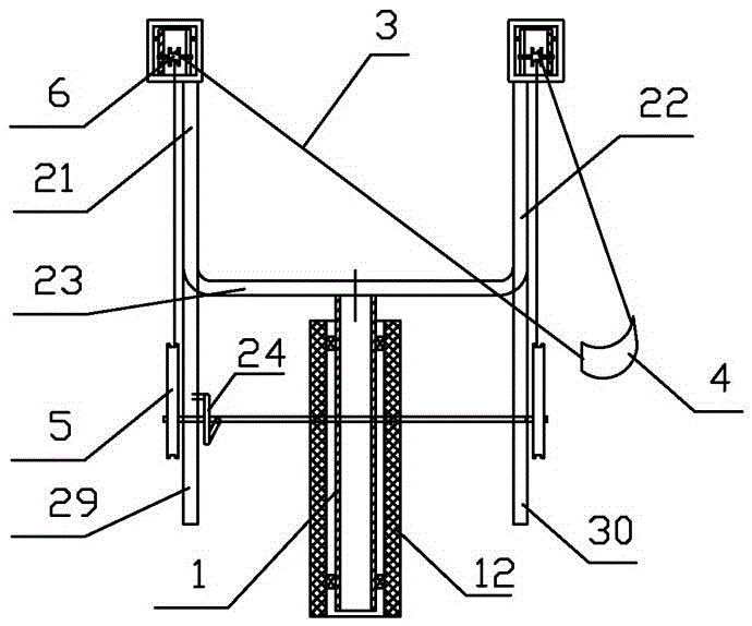
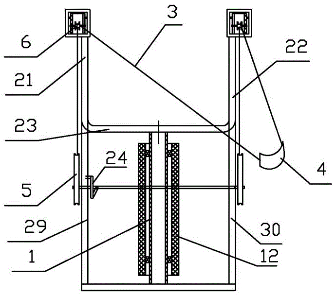
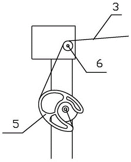
[0020] Such as figure 1 As shown, the eccentric power-assisted slingshot of the present invention includes a handle 1 and a bow body 2 installed on the upper end of the handle. The bow body 2 includes a symmetrically arranged left bow body 21 and a right bow body 22. The left bow body 21 and the lower end of the right bow body 22 are fixedly connected together through the bow body connecting rod 23, the bow body 2 is provided with a rubber band 3, and the middle of the rubber band 3 is provided with a bullet pocket 4, the left bow body 21 and the right bow body The side of body 22 is respectively equipped with eccentric wheel 5 through hinge shaft, and pulley 6 is respectively installed on the upper end of left bow body 21 and right bow body 22, as image 3 , Figure 4 As shown, the end of the rubber band 3 goes around the pulley 6 and is connected to the eccentric wheel 5 .

[0021] Such as Figure 5 As shown, the edge of the eccentric wheel 5 has wire grooves, and the hin...


PUM


Abstract

The invention relates to sporting goods and in particular relates to an eccentric boosting type slingshot. The eccentric boosting type slingshot comprises a handle and a slingshot body mounted at the upper end of the handle, wherein the slingshot body comprises a left slingshot body and a right slingshot body, which are arranged symmetrically; the lower ends of the left slingshot body and the right slingshot body are fixedly connected together through a slingshot body connection rod; the slingshot body is provided with a rubber band; a shot bag is arranged in the middle of the rubber band; eccentric wheels are mounted under the left slingshot body and the right slingshot body respectively through hinging shafts; pulleys are mounted at the upper ends of the left slingshot body and the right slingshot body respectively; and the end part of the rubber band is connected onto the eccentric wheels in a manner of winding around the pulleys. According to the boosting type slingshot provided by the invention, the moment of the rubber band is adjusted by adopting the eccentric wheels, and the boosting type slingshot is compact in structure and strong in manipulation performance; and with the adoption of the horizontally rotary slingshot body, the slingshot body can keep vertical with an alignment line and elastic force of the rubber band on the two sides of the shot bag is balanced, so that the shooting accuracy is improved.

Description

technical field [0001] The invention relates to a sporting goods, in particular to an eccentric power-assisted slingshot. Background technique [0002] Slingshot is a kind of commonly used sports and game supplies. Common slingshot is made of a Y-shaped bow body. The two ends of the bow body are tied with rubber bands. The power of a slingshot depends on the elastic force and length of the rubber band, but due to the limitation of the human body's arm span, the length of the rubber band cannot be extended infinitely. The stretched length of the rubber band is proportional to the elastic force. The force is high, often accompanied by shaking, which is not conducive to aiming. After the bullet pocket is released, the driving force of the rubber band on the bullet pocket decreases sharply. These factors are not conducive to accurate shooting. In addition, the bullet pocket is set in the middle of the rubber band. During use, the bow body of the slingshot is required to be perp...

Claims


Application Information

Patent Timeline
Patent Type & Authority Applications(China)
IPC IPC(8): A63H33/18
CPCA63H33/18
Inventor 孔德庆
Owner 扬州捷兴智能科技有限公司
Learn More