
Upper cover of electric pressure cooker and electric pressure cooker

A technology of electric pressure cooker and pot cover, which is applied in the direction of pressure cooker, etc. It can solve the problems of complex installation structure of pot cover and inner cover, affecting the reliability of electric pressure cooker opening, and low assembly efficiency of electric pressure cooker, so as to improve assembly efficiency and assembly speed Fast, fast molding effect

Inactive Publication Date: 2016-06-15
FOSHAN SHUNDE MIDEA ELECTRICAL HEATING APPLIANCES MFG CO LTD +1
View PDF7 Cites 58 Cited by
  • Summary
  • Abstract
  • Description
  • Claims
  • Application Information

AI Technical Summary

Problems solved by technology

[0003] 1. In the above structure, the installation structure of the pot cover and the inner cover is relatively complicated, resulting in low assembly efficiency of the electric pressure cooker;
[0004] 2. The hanging shaft is installed on the metal pot cover. During the use of the pot cover, because the hanging shaft and the chute are respectively located on the periphery of the pot cover and the inner cover (away from the center of the pot cover), the matching hanging shaft and the When the shift fork is used as the driving structure for opening and closing the cover, it is easy to cause the suspension shaft to be stuck in the chute, which seriously affects the reliability of opening the cover of the electric pressure cooker;
[0005] 3. Part of the pot cover and the inner cover are not detachable. Users cannot disassemble and clean the pot cover after using the electric pressure cooker, and its practicability is obviously insufficient.

Method used


Image

  • Upper cover of electric pressure cooker and electric pressure cooker
  • Upper cover of electric pressure cooker and electric pressure cooker
  • Upper cover of electric pressure cooker and electric pressure cooker

Examples


Embodiment Construction

[0033] In order to understand the above-mentioned purpose, features and advantages of the present invention more clearly, the present invention will be further described in detail below in conjunction with the accompanying drawings and specific embodiments. It should be noted that, in the case of no conflict, the embodiments of the present application and the features in the embodiments can be combined with each other.

[0034] In the following description, many specific details are set forth in order to fully understand the present invention. However, the present invention can also be implemented in other ways than described here. Therefore, the protection scope of the present invention is not limited by the specific implementation disclosed below. Example limitations.

[0035] The upper cover of the electric pressure cooker according to some embodiments of the present invention will be described below with reference to the accompanying drawings.

[0036] The embodiment of o...


PUM


Abstract

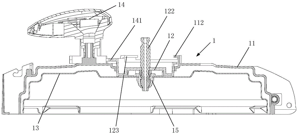
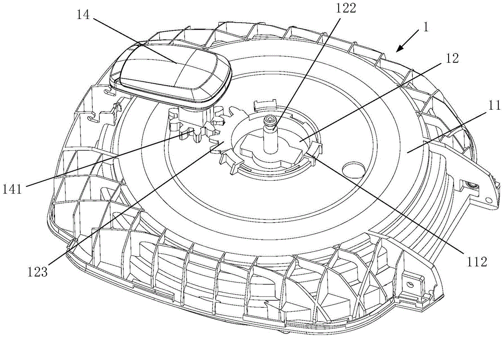
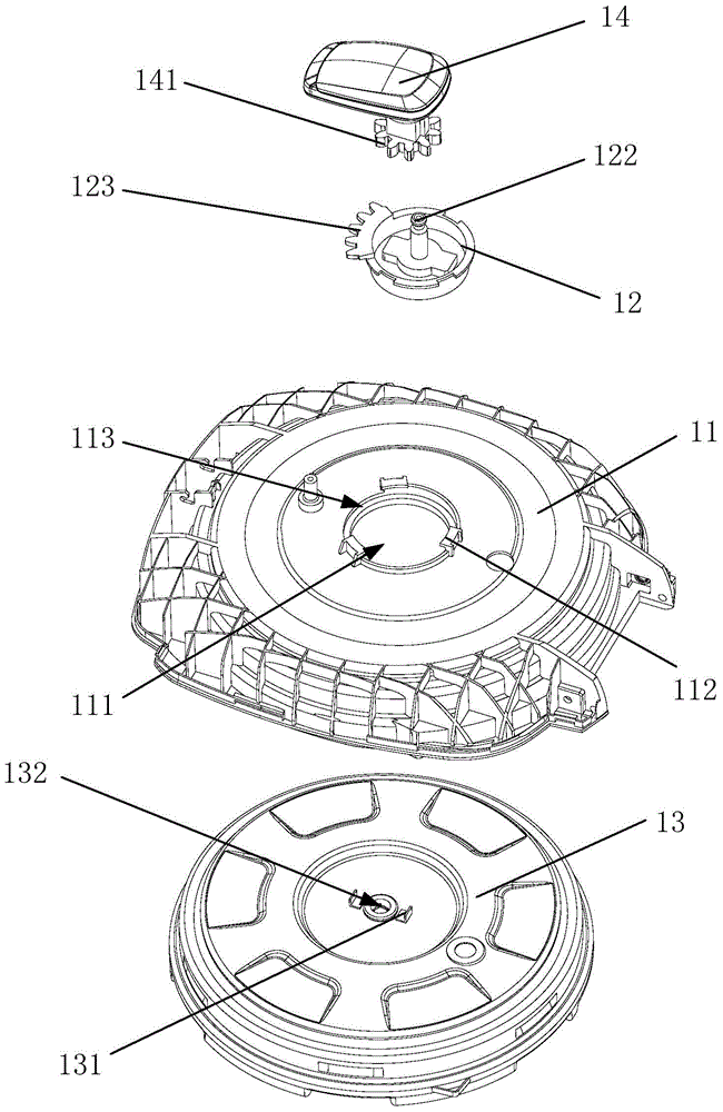
The invention provides an upper cover of an electric pressure cooker and the electric pressure cooker. The upper cover of the electric pressure cooker includes: an inner cover, which has a mounting hole in the middle; a pivot, which is installed at the mounting hole and can rotate around the axis of the mounting hole; a pot cover, which is located below the inner cover and connected to the pivot. And the pivot and the pot cover can rotate together; and the handle is located above the inner cover and is rotatably installed on the inner cover, and the handle is on the side of the mounting hole and the pivot; wherein, one of the handle and the pivot is provided with The first transmission part and the other are provided with a second transmission part, and the first transmission part and the second transmission part are engaged in gear transmission to assist in realizing the rotation of the handle drive pivot and the pot cover together. The upper cover of the electric pressure cooker provided by the present invention has a simple installation structure; in addition, gear transmission is adopted between the handle and the pivot shaft, and the transmission performance is stable and reliable, thereby improving the stability of the electric pressure cooker when opening and closing the cover, and better ensuring the safety of users. use experience.

Description

technical field [0001] The invention relates to the field of household appliances, more specifically, to an upper cover of an electric pressure cooker and an electric pressure cooker including the upper cover. Background technique [0002] In the existing square-shaped electric pressure cooker, the pot cover is provided with pot teeth that are fastened with the pot body, three suspension shafts are provided on the periphery of the pot cover, and three chutes are correspondingly provided on the inner cover, and the suspension shaft and the chute In addition, the inner cover is provided with a handle, and the handle is provided with a shift fork matched with the suspension shaft, and the shift fork is matched with the upper end of the suspension shaft. But there is following defective in prior art: [0003] 1. In the above structure, the installation structure of the pot cover and the inner cover is relatively complicated, resulting in low assembly efficiency of the electric ...

Claims


Application Information

Patent Timeline
IPC IPC(8): A47J27/08
Inventor 吴建新陈华亮
Owner FOSHAN SHUNDE MIDEA ELECTRICAL HEATING APPLIANCES MFG CO LTD
Learn More