Satellite accessory vibration flexible moment simulator based on balance beam
A balance beam and simulator technology, applied in simulators, instruments, control/regulation systems, etc., can solve the problems of inaccurate torque control, small control range, small torque, etc., and achieve large controllable range, direct and accurate control, The effect of high torque
- Summary
- Abstract
- Description
- Claims
- Application Information
AI Technical Summary
Problems solved by technology
Method used
Image
Examples
specific Embodiment approach 1
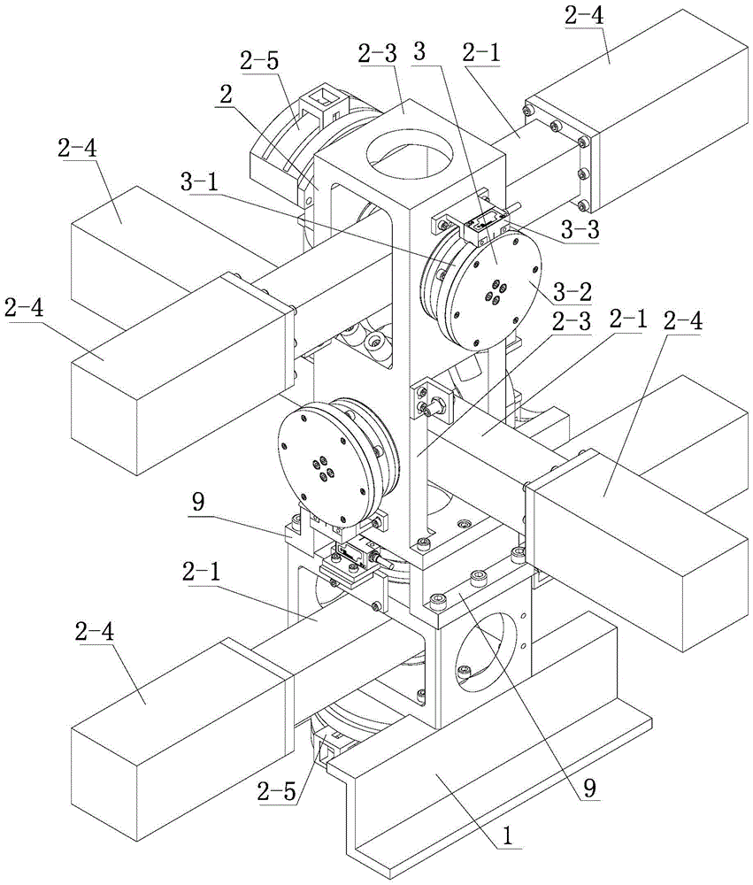
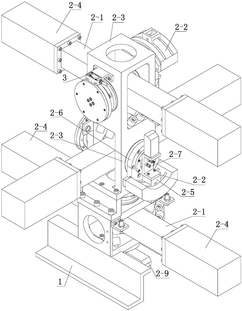
[0011] Specific implementation mode one: combine Figure 1-Figure 4 Illustrate that a satellite accessory vibration and flexure moment simulator based on a balance beam in this embodiment includes a base 1, three balance beam systems 2 and three circular grating systems 3;
[0012] Three balance beam systems 2 are vertically arranged and assembled into a triaxial moment generating mechanism, and the triaxial moment generating mechanism is installed on the base 1;
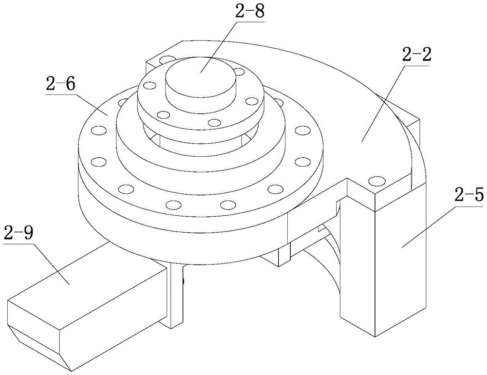
[0013] Each balance beam system 2 includes a balance beam 2-1, a drive mechanism 2-2, a base 2-3 and two balance weights 2-4; two adjacent balance beams in the three balance beams 2-1 The length directions of 2-1 are perpendicular; each driving mechanism 2-2 includes a motor 2-5, a motor base 2-6, a motor connection block 2-7 and a shaft 2-8;
[0014] The motor 2-5 on each balance beam system 2 is installed on the motor base 2-6, the motor base 2-6 is installed on the base 2-3, and the output end of the motor 2-5 i...
specific Embodiment approach 2
[0016] Specific implementation mode two: combination Figure 1-Figure 2 To illustrate, the swing angle range of the balance beam 2 - 1 in this embodiment is -30° to 30°. With such arrangement, this embodiment effectively solves the problem of driving with large inertia. Others are the same as in the first embodiment.
specific Embodiment approach 3
[0017] Specific implementation mode three: combination Figure 1-Figure 2 Explain that each circular grating system 3 in this embodiment includes a circular grating 3-1, a circular grating seat 3-2 and a circular grating reading head 3-3; the other end of the shaft 2-8 is connected to the circular grating seat 3-2, A circular grating 3-1 is installed on the circular grating seat 3-2, and a circular grating reading head 3-3 is installed on the circular grating 3-1. Such setting can realize the measurement of the rotation angle of the shaft, form feedback control, realize real-time measurement, and make the control more direct and accurate. Others are the same as in the first or second embodiment.
PUM
 Abstract
Description
Claims
Application Information
 - Generate Ideas
- Intellectual Property
- Life Sciences
- Materials
- Tech Scout
- Unparalleled Data Quality
- Higher Quality Content
- 60% Fewer Hallucinations
Browse by: Latest US Patents, China's latest patents, Technical Efficacy Thesaurus, Application Domain, Technology Topic, Popular Technical Reports.
© 2025 PatSnap. All rights reserved.Legal|Privacy policy|Modern Slavery Act Transparency Statement|Sitemap|About US| Contact US: help@patsnap.com


