
Clusters of polynomials for data points

A technology for rotating electrical machines and stators, which is applied in the field of stators to achieve the effect of lowering the height position and suppressing the increase in axial size

Active Publication Date: 2016-06-01
MITSUBISHI ELECTRIC CORP
View PDF6 Cites 14 Cited by
  • Summary
  • Abstract
  • Description
  • Claims
  • Application Information

AI Technical Summary

Problems solved by technology

Therefore, the size of the terminal unit including the bus bar increases, causing interference with peripheral parts of the motor. Therefore, a technique for compactly storing the terminal unit near the motor is required.

Method used


Image

  • Clusters of polynomials for data points
  • Clusters of polynomials for data points
  • Clusters of polynomials for data points

Examples


Embodiment approach 1

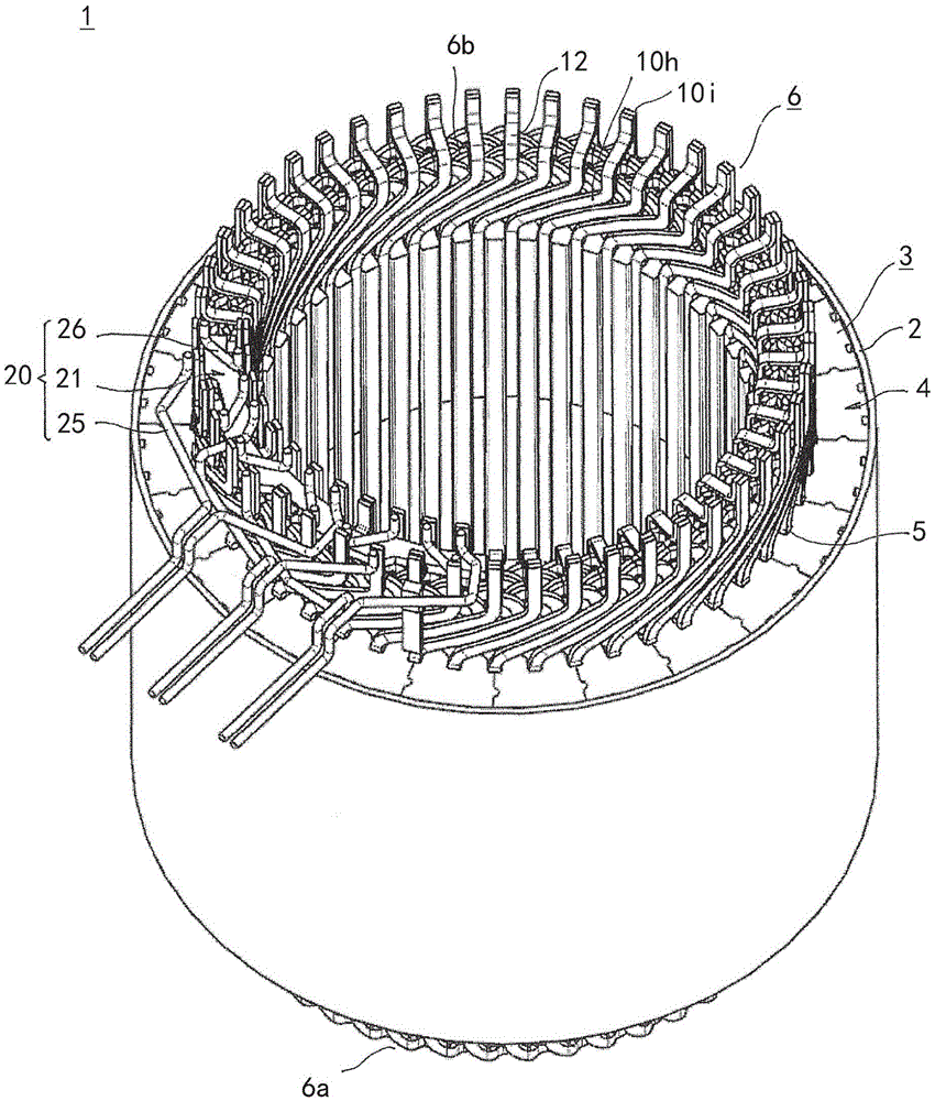
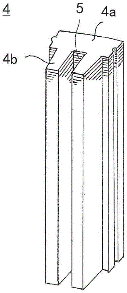
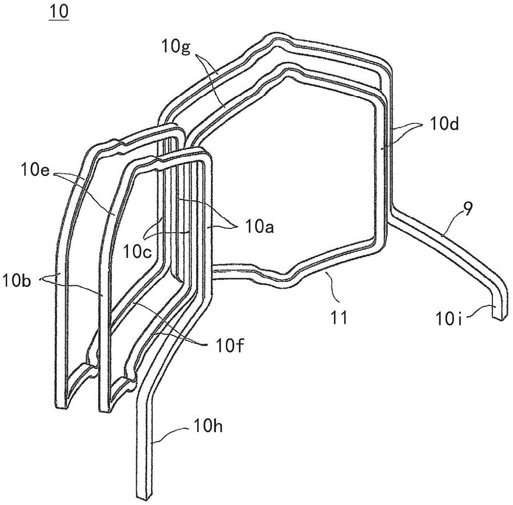
[0033] figure 1 is a perspective view showing a stator of a rotating electrical machine according to Embodiment 1 of the present invention, figure 2 is a perspective view showing a core block constituting a stator core in the stator of the rotating electrical machine according to the first embodiment, image 3 is a perspective view showing a winding body constituting the stator winding in the stator of the rotating electric machine according to the first embodiment, Figure 4 is a front view showing a winding body constituting the stator winding in the stator of the rotating electric machine according to the first embodiment, Figure 5 It is an end view of the winding body constituting the stator winding in the stator of the rotating electric machine according to the first embodiment viewed from the second coil end side, Image 6 It is an end view of main parts in a state in which three winding bodies constituting the stator winding in the stator of the rotating electrical ...


PUM


Abstract

A method, system and storage device are generally directed to determining for each of a plurality of data points, a neighborhood of data points about each such data point. For each such neighborhood of data points, a projection set of polynomials is generated based on candidate polynomials. The projection set of polynomials evaluated on the neighborhood of data points is subtracted from the plurality of candidate polynomials evaluated on the neighborhood of data points to generate a subtraction matrix of evaluated resulting polynomials. The singular value decomposition of the subtraction matrix is then computed. The resulting polynomials are clustered into multiple clusters and then partitioned based on a threshold.

Description

technical field [0001] The present invention relates to stators of rotating electrical machines, such as electric motors, generators, etc., and in particular to terminal units comprising busbars connected to phase windings of the stator windings. Background technique [0002] In generators used in EVs (electric vehicles) and PEVs (pure electric vehicles), large currents are passed through the stator windings, so busbars with a large cross-sectional area are used. Therefore, the size of the terminal unit including the bus bars increases, and interference with peripheral parts of the motor occurs. Therefore, a technique for compactly housing the terminal unit near the motor is required. [0003] In view of the above situation, the busbars are arranged in two layers in the vertical direction and arranged in a zigzag or diagonal shape, and the insulating members are used to insulate and cover each busbar to form a wiring unit, thereby realizing the compactness of the wiring unit...

Claims


Application Information

Patent Timeline
Patent Type & Authority Applications(China)
IPC IPC(8): H02K3/04
CPCH02K1/16H02K3/12H02K3/28H02K3/50H02K15/0081H02K15/045H02K2203/09H02K2213/03H02K1/12
Inventor 中村成志冈本省吾坂上笃史
Owner MITSUBISHI ELECTRIC CORP
Learn More