
A Communication System for CAN Bus Precise Timing and Pipeline Testing

A CAN bus, communication system technology, applied in the field of communication systems, to achieve the effects of improving communication reliability, ensuring reliable transmission, and facilitating problem location

Active Publication Date: 2019-05-17
BEIJING RES INST OF PRECISE MECHATRONICS CONTROLS +1
View PDF7 Cites 0 Cited by
  • Summary
  • Abstract
  • Description
  • Claims
  • Application Information

AI Technical Summary

Problems solved by technology

There is no similar CAN bus precise timing communication solution, especially in terms of pipeline testing and hot-swapping testing, it is still in a blank state

Method used


Image

  • A Communication System for CAN Bus Precise Timing and Pipeline Testing
  • A Communication System for CAN Bus Precise Timing and Pipeline Testing
  • A Communication System for CAN Bus Precise Timing and Pipeline Testing

Examples


Embodiment Construction

[0048] Below in conjunction with accompanying drawing and embodiment a kind of that the present invention provides is introduced:

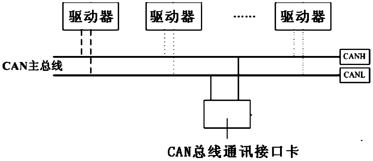
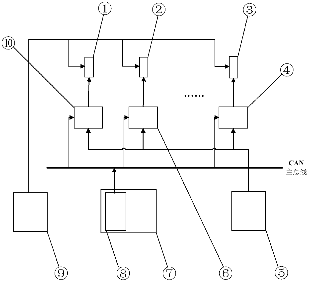
[0049]A CAN bus precise timing and pipeline test communication system, including actuator A1, actuator B2, actuator C3, driver A4, driver B6, driver C10, ground control power supply module A5, with CAN bus communication Interface card 8, CAN bus timing communication system 7, ground power supply module B9 and CAN bus, wherein ground power supply module B9 is connected to actuator A1, actuator B2, and actuator C3 respectively, and ground control power supply module A5 They are respectively connected to driver A4, driver B6 and driver C10, the CAN bus is connected to driver A4, driver B6 and driver C10 respectively, actuator A1 is connected to driver C10, actuator B2 is connected to driver B6, and actuator C3 is connected to driver A4 is connected, with a CAN bus communication interface card 8 set on the CAN bus timing communication system 7, with a...


PUM


Abstract

The invention belongs to the technical field of a communication system, and specifically relates to a CAN bus accurate timing and assembly line testing communication system and method which can achieve high-reliability, high-precision, assembly line type and hot plug type communication with a servo driver. The system comprises an actuator A, an actuator B, an actuator C, a driver A, a driver B, a driver C, a ground control power supply module A, a CAN bus communication interface card, a CAN bus timing communication system, a ground power power-supply module B and a CAN bus. The ground power power-supply module B is connected with the actuator A, the actuator B and the actuator C. The ground control power supply module A is connected with the driver A, the driver B and the driver C. The CAN bus is connected with the driver A, the driver B and the driver C. The actuator A is connected with the driver C, the actuator B is connected with the driver B, and the actuator C is connected with the driver A.

Description

technical field [0001] The invention belongs to the technical field of communication systems, and in particular relates to a communication system and method for CAN bus precise timing and pipeline testing Background technique [0002] The servo drive is a power device that drives the actuator of the servo mechanism. It is mainly used to receive the CAN bus command sent by the front-end device-the controller, and to drive the back-end device by converting the CAN command signal into a high-power drive signal in real time. actuator movement. And transmit CAN bus data to the controller in real time to complete command transmission and information feedback. It is one of the core components of the high-precision and high-speed operation of the servo mechanism. [0003] The CAN bus command signal sent and received by the servo drive has a command timing accuracy of millisecond level and a data transmission accuracy of microsecond level. How to test it with high precision has bec...

Claims


Application Information

Patent Timeline
Patent Type & Authority Patents(China)
IPC IPC(8): G05B19/418
Inventor 张蕾徐武欣李钢谢伟
Owner BEIJING RES INST OF PRECISE MECHATRONICS CONTROLS
Learn More