An automatic action restraint

A restraint and automatic technology, which is applied in the direction of weapons for capturing animals and weapons without explosives composed of ropes and heavy objects, can solve the problems of poor ease of use and low degree of automation.

Active Publication Date: 2017-03-29
重庆警察学院
View PDF7 Cites 0 Cited by
  • Summary
  • Abstract
  • Description
  • Claims
  • Application Information

AI Technical Summary

Problems solved by technology

[0003] In view of this, the purpose of the present invention is to provide an automatic action restraint to solve the technical problems of the prior art that the action restraint needs to be used at close range, has poor ease of use, and has a low degree of automation.

Method used


Image

  • An automatic action restraint
  • An automatic action restraint
  • An automatic action restraint

Examples


Embodiment Construction

[0019] The present invention will be further described below in conjunction with the accompanying drawings and embodiments.

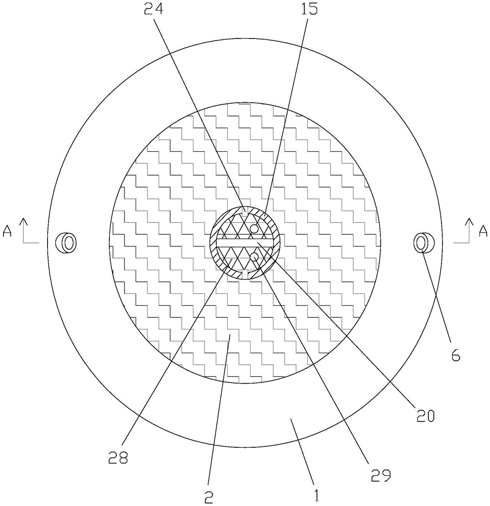
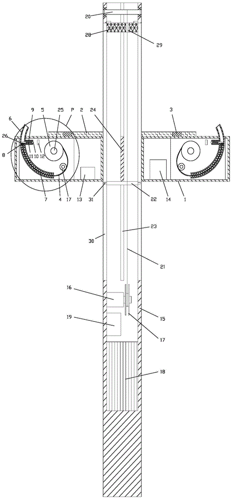
[0020] As shown in the figure, the automatic movement restraint of this embodiment includes a binding device and a binding device launching mechanism;

[0021] The binding device includes a housing 1, an adhesive layer 2 and a pressure sensor 3 are arranged on one side of the housing;

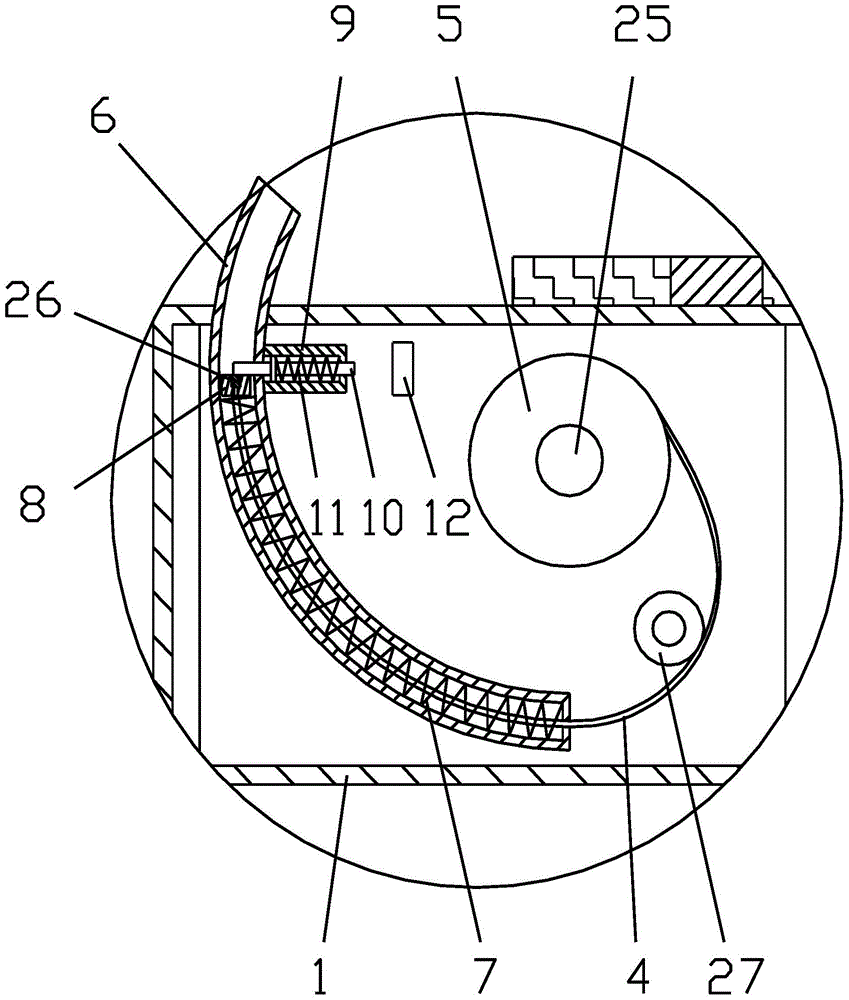
[0022] Two sets of symmetrically arranged rope launching mechanisms are provided in the housing, and the rope launching mechanism includes a rope 4, a rotating sheave 5, an arc guide tube 6, and an arc spring whose bending shape is consistent with the arc guide tube. 7, permanent magnet 8, and lock pin device, described lock pin device comprises guide sleeve 9 fixedly arranged, the lock pin 10 that slides with guide sleeve, is arranged on the back-moving spring 11 that applies thrust to lock pin in guide sleeve , and the electromagnet 12 opposite to the end of the guide...


PUM


Abstract

The invention discloses an automatic movement restricting device. The automatic movement restricting device comprises a binding device and a binding device launching mechanism; the binding device comprises a shell, an adhesive layer, a pressure sensor and binding rope launching mechanisms which are arranged symmetrically, and each binding rope launching mechanism comprises a binding rope, a rotating grooved pulley, an arc-shaped guide tube, an arc-shaped spring, of which the bent shape is consistent with that of the arc-shaped guide tube, a permanent magnet and a locking pin device; the binding device launching mechanism comprises a straight launching tube, a first motor, a wind wheel, a rotating shaft, a pull rope and a drawing plate which is fixed on the pull rope. During the arresting of a suspect, the binding device on the straight launching tube is firstly aimed at the thigh or upper body of the suspect by a police officer, and the motor drives the drawing plate to push the binding device to fly to the suspect, so that the automatic movement restricting device can be used in a distant range, and the object hit rate is high; the binding device is attached to the suspect through the adhesive layer and achieves automatic binding, so that the convenience of use is good, and the degree of automation is high.

Description

technical field [0001] The invention relates to a police device, in particular to an automatic action restraint. Background technique [0002] In the prior art, the automatic action restraints used by the police mainly include handcuffs, steel forks, restraint belts, etc., but these types of automatic action restraints have their own shortcomings: 1. The handcuffs can only be used after close contact, which is easy Casualties and diseases are caused; 2. Steel forks and other arresting equipment are large in size and heavy in weight, which are inconvenient to carry and use, and require the cooperation of multiple people to be effective; The use process is cumbersome and requires close contact; 4. The automation degree of the existing automatic action restraint is relatively weak. Contents of the invention [0003] In view of this, the object of the present invention is to provide an automatic movement restraint to solve the technical problems that the movement restraints i...

Claims


Application Information

Patent Timeline
IPC IPC(8): F41B15/10
CPCF41B15/10
Inventor 陈新平
Owner 重庆警察学院
Why Eureka
Try Eureka