
Spliced assembly and locking attaching module thereof

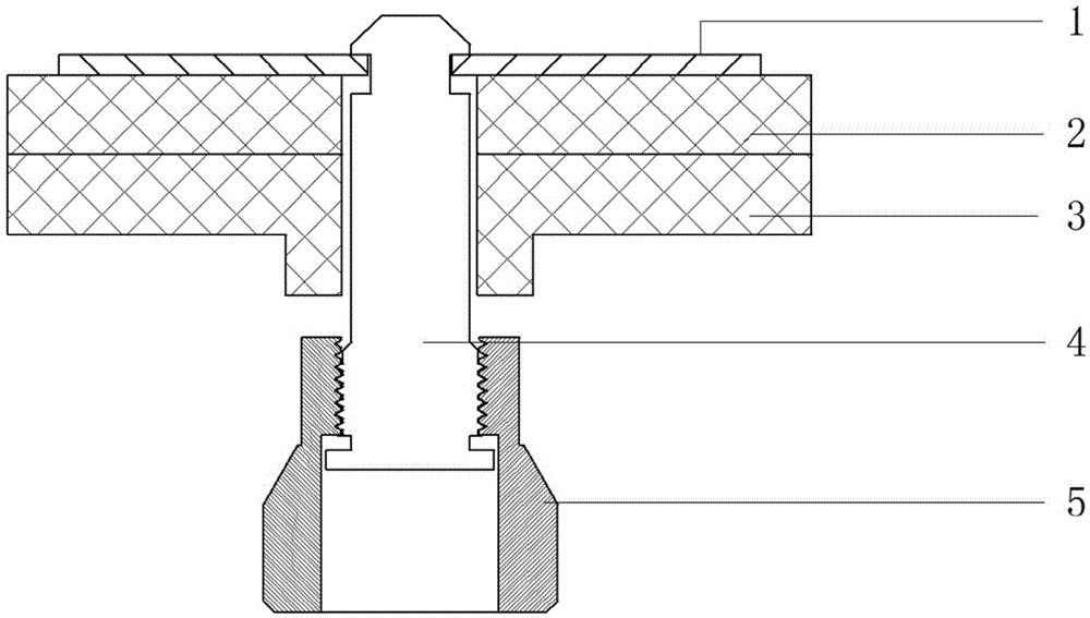
A locking and module technology, which is applied in the electronic field, can solve the problems of inconsistent size of display module gaps, difficulty in processing, high processing cost, and error in box processing accuracy, so as to avoid bright lines and dark lines and reduce the accuracy of external dimensions Requirements, the effect of easy assembly and disassembly

Inactive Publication Date: 2016-05-25
DONGGUAN DONGSHAN PRECISION MFG CO LTD
View PDF8 Cites 2 Cited by
  • Summary
  • Abstract
  • Description
  • Claims
  • Application Information

AI Technical Summary

Problems solved by technology

[0003] This solution has the following disadvantages: 1. It only has a locking function; 2. Due to the high precision of the box body, high-precision CNC machining is required to ensure the accuracy of the box shape and size, which makes processing difficult and high in processing costs; 3. There is an error in the processing accuracy of the cabinet, which leads to inconsistent gap sizes between the display modules when multiple groups of display modules are combined, causing bright and dark lines on the display screen. However, the current structure cannot adjust the gap between the cabinets. Eliminate this bad phenomenon

Method used


Image

  • Spliced assembly and locking attaching module thereof
  • Spliced assembly and locking attaching module thereof
  • Spliced assembly and locking attaching module thereof

Examples


Embodiment Construction

[0021] In order to make the object, technical solution and advantages of the present invention clearer, various embodiments of the present invention will be described in detail below in conjunction with the accompanying drawings. However, those of ordinary skill in the art can understand that, in each implementation manner of the present invention, many technical details are provided for readers to better understand the present application. However, even without these technical details and various changes and modifications based on the following implementation modes, the technical solution claimed in each claim of the present application can be realized.

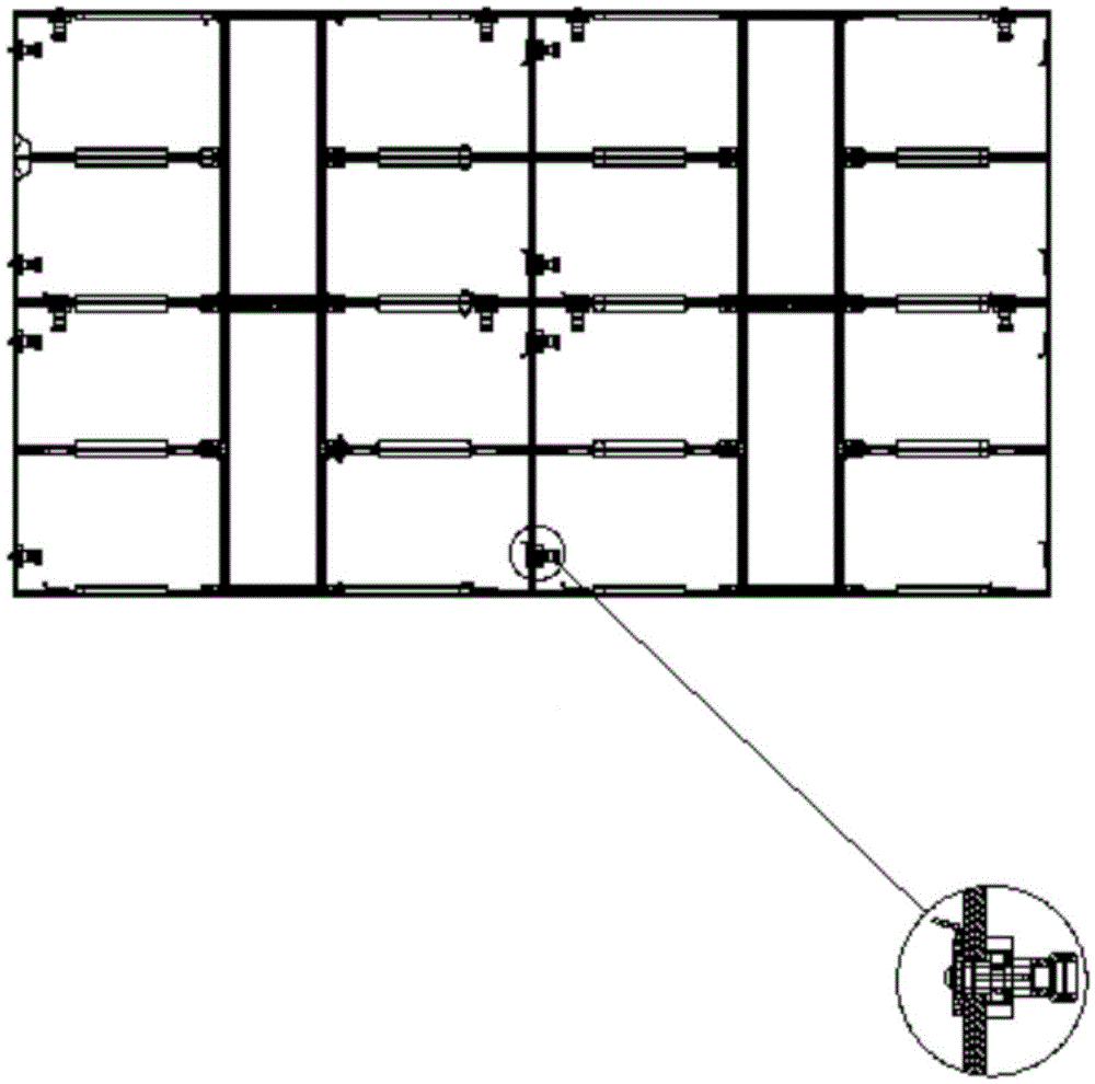
[0022] The first embodiment of the present invention relates to a locking module. Such as figure 2 As shown, the figure contains a plurality of display cabinets, and two adjacent display cabinets use the locking module ( figure 2 The enlarged area in ) are spliced ​​together, wherein, when the display screens are placed ...


PUM


Abstract

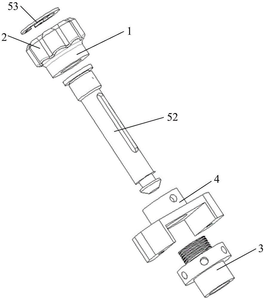
The invention relates to the technical field of electronics, and discloses a locking attaching module and a spliced assembly with the same. The locking attaching module comprises a first to-be-locked piece with a first lock hole, a second to-be-locked piece, an adjustment rod, an adjustment base and a locking assembly. The adjustment base is arranged on the first to-be-locked piece, the adjustment rod is adjustably positioned to the adjustment base and penetrates through the first lock hole, and the locking assembly sequentially penetrates through the adjustment rod and the second to-be-locked piece so as to attach the second to-be-locked piece to the first to-be-locked piece in a locked mode. When moving in the direction of the second to-be-locked piece, the adjustment rod can extend out of the first lock hole and abut against the second to-be-locked piece so as to adjust a locking attaching gap between the first to-be-locked piece and the second to-be-locked piece. By means of the structure, the locking attaching gap can be subjected to fine adjustment, the requirement for the accuracy of the outline size of the to-be-connected pieces is reduced accordingly, and then the machining difficulty and the machining cost of the to-be-locked pieces are reduced; bright lines and dark lines caused by the error of the outline size of the to-be-locked pieces and generated after multiple to-be-locked pieces are combined are avoided.

Description

technical field [0001] The invention relates to the field of electronic technology, in particular to a splicing assembly and a locking module thereof. Background technique [0002] With the development of science and technology, the application of LED display is becoming more and more extensive. The assembling design scheme of the traditional LED display screen includes installing a lock socket 1, a first box body 2, a second box body 3, a pull rod 4, and a tightening nut mechanism 5. The slot at one end of the pull rod 4 engages with the installation lock nut 1 , and the thread at the other end combines with the tightening nut mechanism 5 . Then, the pull rod 4 is driven downward by rotating the tightening nut mechanism 5 , thereby locking the first box body 2 and the second box body 3 . [0003] This solution has the following disadvantages: 1. It only has a locking function; 2. Due to the high precision of the box body, high-precision CNC machining is required to ensure...

Claims


Application Information

Patent Timeline
IPC IPC(8): F16B2/06G09F9/33
CPCF16B2/065G09F9/33
Inventor 梁文骥伍亮
Owner DONGGUAN DONGSHAN PRECISION MFG CO LTD
Learn More