Combined sprue basin

A sprue basin and combined technology, which is applied in the direction of casting molding equipment, metal processing equipment, and mold composition, can solve the problems of reducing the ratio of sand to iron and the amount of sand eaten by the mold, and achieve the goal of reducing the amount of sand used Effect

Active Publication Date: 2018-11-27
KOCEL EQUIP
View PDF8 Cites 0 Cited by
  • Summary
  • Abstract
  • Description
  • Claims
  • Application Information

AI Technical Summary

Problems solved by technology

[0006] Aiming at the problems existing in the related art, the present invention overcomes the defects of excessive sand intake in the mold caused by ensuring the casting pressure angle and placing the filter screen in the prior art, and provides a combined type that can reduce the ratio of sand to iron. The sprue basin, the combined sprue basin can ensure the height of the remaining pressure head without increasing the amount of sand intake

Method used


Image

  • Combined sprue basin
  • Combined sprue basin
  • Combined sprue basin

Examples


Embodiment Construction

[0025] Embodiments of the present invention will be described in detail with reference to the drawings.

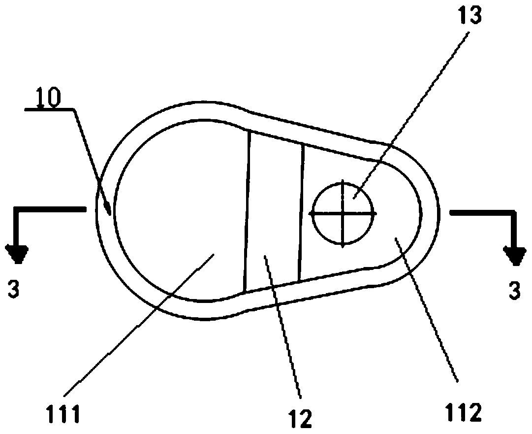
[0026] refer to figure 1 , the present invention provides a combined sprue basin, the combined sprue basin is used to pour molten iron into the mold, and it is characterized in that it includes: a sprue basin 10; a sprue seat 2, and the sprue seat 2 is nested in the sprue basin 10, and between the sprue basin 10 and the upper box of the mold (not shown). The combined sprue basin of the present invention uses the sprue seat 2 between the sprue basin 10 and the mold to avoid the problem of increasing the amount of sand eaten by the mold in the prior art in order to ensure the height of the remaining pressure head, that is, the cast The mold increases the height of the remaining pressure head without increasing the amount of sand consumed, reduces the amount of sand used in the mold, and reduces the waste of resources and costs.

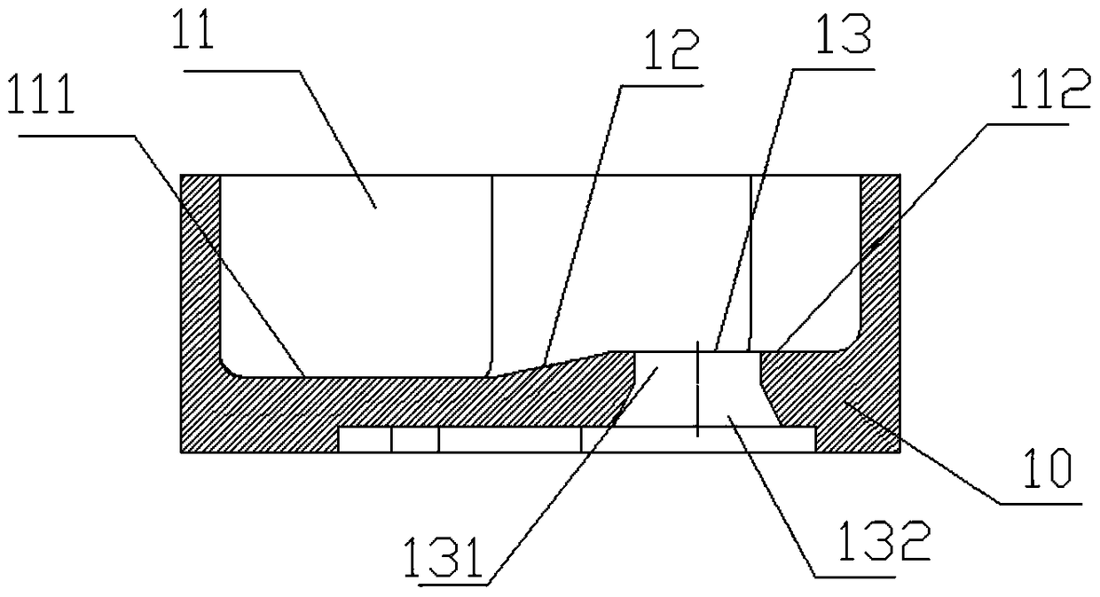
[0027] refer to Figure 2-3 The sprue basi...


PUM


Abstract

The invention provides a combined type pouring basin. The combined type pouring basin is used for pouring molten iron for casting moulds, and is characterized by comprising a pouring basin body and a pouring seat; the pouring seat is nested at the bottom of the pouring basin body and is positioned between the pouring basin body and an upper box of the casting moulds. The invention aims to provide the combined pouring basin which guarantees the heights of the rest pressure heads on the premise of not increasing mold thickness of the casting moulds.

Description

technical field [0001] The invention relates to a sprue basin, in particular to a combined sprue basin capable of reducing the sand-iron ratio, and the sprue basin can be used for casting iron castings with a weight less than 800kg. Background technique [0002] With the application of conformal sand boxes and special core iron in the casting process, the current casting technology is developing in the direction of reducing the ratio of sand to iron: on the one hand, it can reduce the amount of resin and curing agent, which can greatly save costs; on the other hand, it can improve The air permeability of the sand mold reduces the amount of gas generated in the mold and improves the quality of the casting. However, in the actual production process, in order to meet the height requirements of the remaining pressure head in the pouring process and the layout requirements of the filter screen in the pouring system, the local sand consumption of the sand mold will increase. [0...

Claims


Application Information

Patent Timeline
Patent Type & Authority Patents(China)
IPC IPC(8): B22C9/08
CPCB22C9/082
Inventor 王洪涛杜文强
Owner KOCEL EQUIP
Why Eureka
Try Eureka