
Angle correcting trowel

A trowel and angle correction technology, which is applied in the field of construction tools, can solve the problem of single function of the trowel, and achieve the effect of straight corner lines

Inactive Publication Date: 2016-05-18
SHAANXI ZHONGHAOYUAN HYDROPOWER ENG CO LTD
View PDF0 Cites 0 Cited by
  • Summary
  • Abstract
  • Description
  • Claims
  • Application Information

AI Technical Summary

Problems solved by technology

[0003] The purpose of the present invention is to provide a kind of correcting angle trowel, which solves the problem of single function in the prior art.

Method used


Image

  • Angle correcting trowel
  • Angle correcting trowel
  • Angle correcting trowel

Examples


Embodiment Construction

[0010] The present invention will be described in detail below in conjunction with the accompanying drawings and specific embodiments.

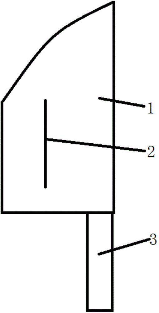
[0011] refer to figure 1 , figure 2 , image 3 The structure of the present invention is to include a rectangular or pointed knife plate 1 and its handle 3, a vertical plate 2 is installed in the middle of any side of the knife plate 1, the vertical plate 2 is parallel to the direction of the knife handle 3, and the vertical plate 2 is parallel to the knife handle. The angle between the two faces of plate 1 is 90°.

[0012] refer to figure 1 , figure 2 , image 3 The working principle of the present invention is that the right angle formed by the vertical plate 3 and the knife plate 1 can be used for the construction correction of the corner line, so that the corner line is more in line with the right angle requirement and looks more beautiful.


PUM


Abstract

The invention discloses an angle correcting trowel. The angle correcting trowel comprises a rectangular or pointed-end tool board and a tool holder, wherein a vertical board is mounted in the middle of any surface of the tool board; the vertical board is parallel to the direction of the tool holder; and an angle between the each of the two surfaces of the vertical board and the tool board is 90 DEG. According to the angle correcting trowel, corner lines can be directly plastered straightly so that the corner lines are straight and a beautiful and elegant construction effect is ensured.

Description

technical field [0001] The invention belongs to the technical field of building tools, and relates to a corner correcting trowel. Background technique [0002] The existing trowel has been used for a long time, and the structure is simple and easy to use. However, due to the fact that it is sometimes necessary to smooth the corners in actual use, for the processing of right-angled corners, only by the experience and technology of workers, some slight errors are prone to occur, resulting in not very straight corners and imperfect right angles. Beautiful, affecting the overall architectural image. Contents of the invention [0003] The object of the present invention is to provide a trowel for correcting angles, which solves the problem of single function of the trowel in the prior art. [0004] The technical solution adopted in the present invention is, a kind of correcting angle tile knife, including rectangular or pointed knife plate and its knife handle, a vertical pla...

Claims


Application Information

Patent Timeline
Patent Type & Authority Applications(China)
IPC IPC(8): E04F21/04
Inventor 何丽
Owner SHAANXI ZHONGHAOYUAN HYDROPOWER ENG CO LTD
Learn More