Groove structure

A card slot and slot technology, applied in the field of the card slot structure with automatic card eject function, can solve problems such as inconvenience in use

Active Publication Date: 2016-05-11
ACER INC
View PDF8 Cites 0 Cited by
  • Summary
  • Abstract
  • Description
  • Claims
  • Application Information

AI Technical Summary

Problems solved by technology

However, in the configuration of the current electronic device, when the user wants to take out the SIM card or the flash memory card from the mobile phone or the electronic device, that is, when performing the withdrawal process of the SIM card or the flash memory card, often Need to go through multiple steps, causing inconvenience in use

Method used


Image

  • Groove structure
  • Groove structure
  • Groove structure

Examples


Embodiment Construction

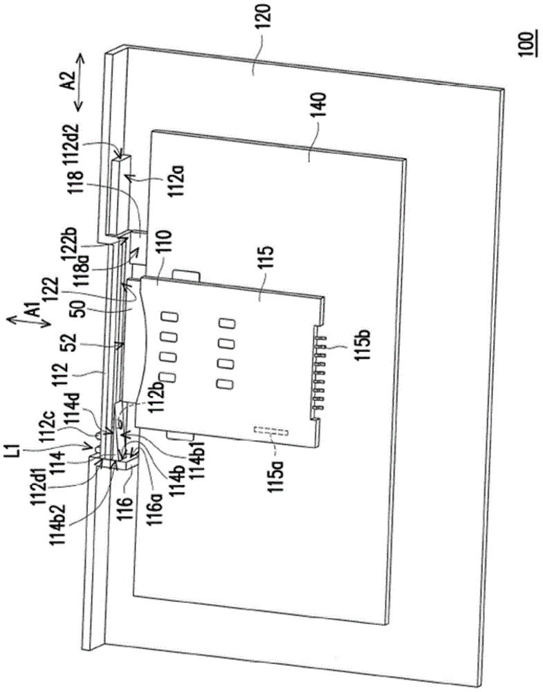
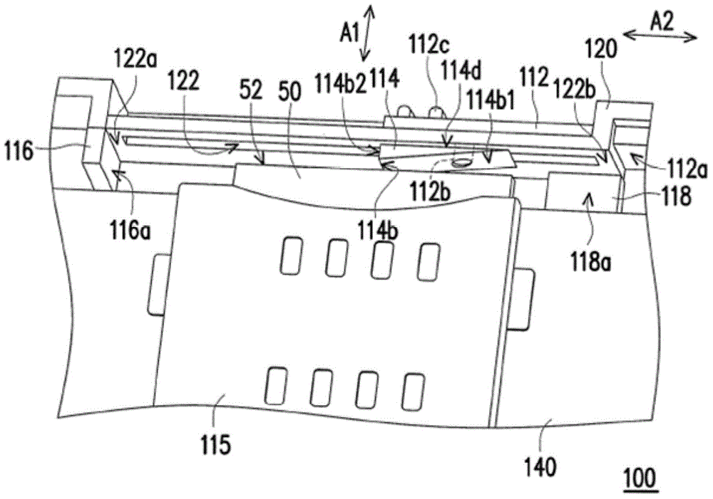
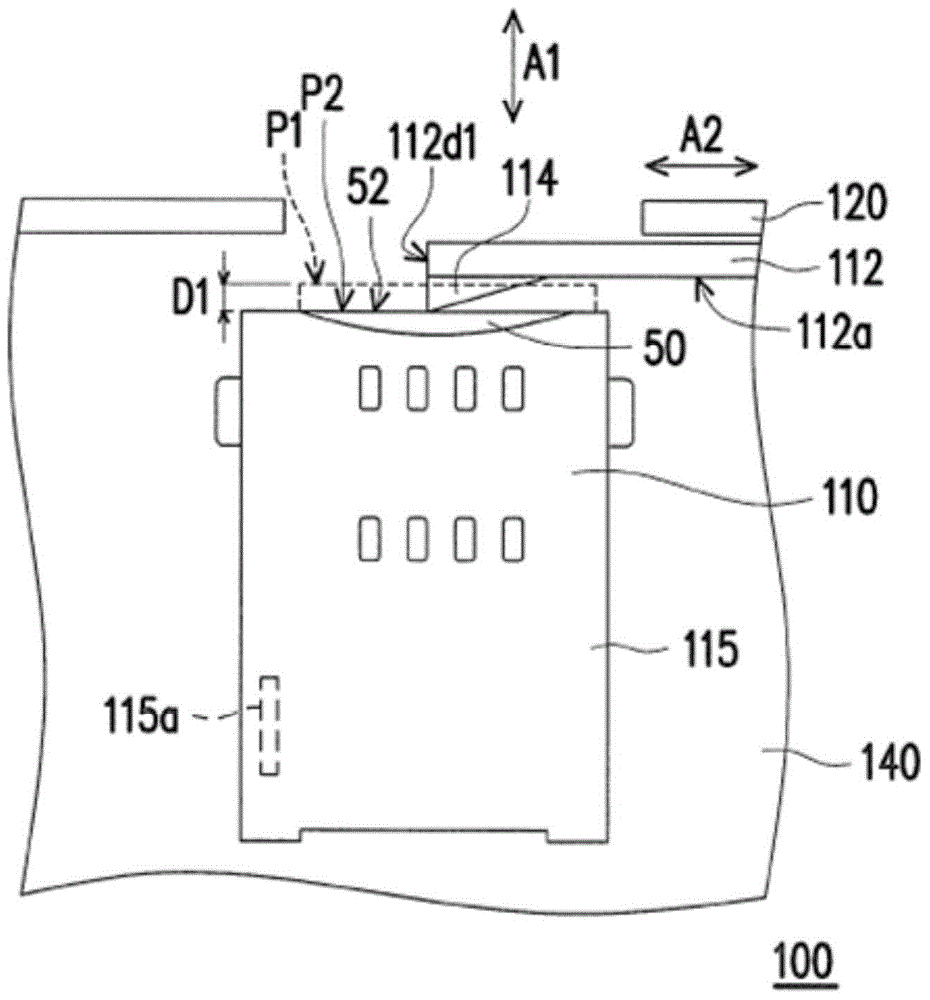
[0047] figure 1 It is a perspective view of the slot structure of an embodiment of the present invention. Please refer to figure 1 , in this embodiment, the slot structure 110 is mounted on the casing 120 of the electronic device 100 . The slot structure 110 includes a slot 115 , a door cover 112 and a pusher 114 , wherein the door cover 112 is slidably passed through the casing 120 . The slot 115 is disposed in the housing 120, and the slot 115 has a push-push type unit 115a, which is only shown in a simplified diagram, and its detailed structural features can be known from the prior art. In addition, the clip 50 is suitable for being inserted into the slot 115 along the first axis A1 through the double-push unit 115a and locked in the slot 115, and is located at the clamping position, or is inserted along the first axis A1 through the double-push unit 115a. exit in slot 115. The door cover 112 is slidably disposed on the casing 120 along the second axis A2 to open or clo...


PUM


Abstract

Provided in the invention is a groove structure assembled into a housing of an electronic device. The groove structure comprises an insertion slot, a door cover, and a push element. The insertion slot is formed in the housing and has a dual-push unit; a clamping element is inserted along a fist axial direction by the dual-push unit and is clamped into the insertion slot or retreats from the insertion slot along the first axial direction by the dual-push unit. The door cover is arranged at the housing in a sliding mode along a second axial direction to open or close the insertion slot. The push element is connected to the door cover and slides with the door cover. When the clamping element is accommodated into the insertion slot and the door cover slides along the second axial direction and the insertion slot is opened, the part of the clamping element is located on the moving path of the push element and thus the clamping element moves along the first axial direction when the push element passes by the clamping element. Moreover, the dual-push unit is triggered; and after the push element moves away from the clamping element, the clamping element retreats from the insertion slot by the dual-push unit.

Description

technical field [0001] The present invention relates to a card slot structure, and in particular to a card slot structure with automatic card withdrawal function. Background technique [0002] With the advancement of technology, digital electronic devices, such as digital cameras, smartphones, tablet PCs, and mobile phones, allow users to obtain required information anytime and anywhere in daily life. In the use of smart phones or mobile phones, the use of a mobile phone number usually needs to correspond to a Subscriber Identity Module (SIM) card to store the identification data of users of mobile phone services and store short messages. data and phone number. On the other hand, consumers have higher and higher requirements for the quality of digital images and digital music, and therefore, users have higher and higher requirements for the capacity of storage media. At present, the capacity of the storage medium built in the electronic device is often limited by the appea...

Claims


Application Information

Patent Timeline
Patent Type & Authority Applications(China)
IPC IPC(8): H01R13/633H01R12/71
Inventor 洪佑宗
Owner ACER INC
Why Eureka
Try Eureka