
Integrated connector for power supply transmission lines, signal transmission lines and lock bodies and integrating method

A power signal and connector technology, which is applied in the direction of connection, two-part connection device, and parts of the connection device, can solve the problem that the stability of the screen installation cannot be optimal, the installation error rate is high, and additional floor space is required and other problems, to achieve the effect of simple and efficient overall construction and installation work

Inactive Publication Date: 2016-05-04
刘剑冰
View PDF7 Cites 4 Cited by
  • Summary
  • Abstract
  • Description
  • Claims
  • Application Information

AI Technical Summary

Problems solved by technology

[0005] When using the above-mentioned technical solutions, a large number of locking devices and power supply and signal connectors often need to be configured around a single display screen. This method is very cumbersome and requires professional installation steps during specific installation and construction. It takes a long time for the installers to complete the installation, and the installation error rate is high. In addition, the above-mentioned method needs to reserve a large space on the back of the large display screen in advance to facilitate the installation personnel to enter and exit and perform installation actions. Therefore, the traditional Large-scale display screens cannot be completely attached to the back support (such as the wall), which requires additional floor space, and the installation stability of the entire screen body cannot be optimal, which is the traditional technology. The main disadvantage of

Method used


Image

  • Integrated connector for power supply transmission lines, signal transmission lines and lock bodies and integrating method
  • Integrated connector for power supply transmission lines, signal transmission lines and lock bodies and integrating method
  • Integrated connector for power supply transmission lines, signal transmission lines and lock bodies and integrating method

Examples


Embodiment Construction

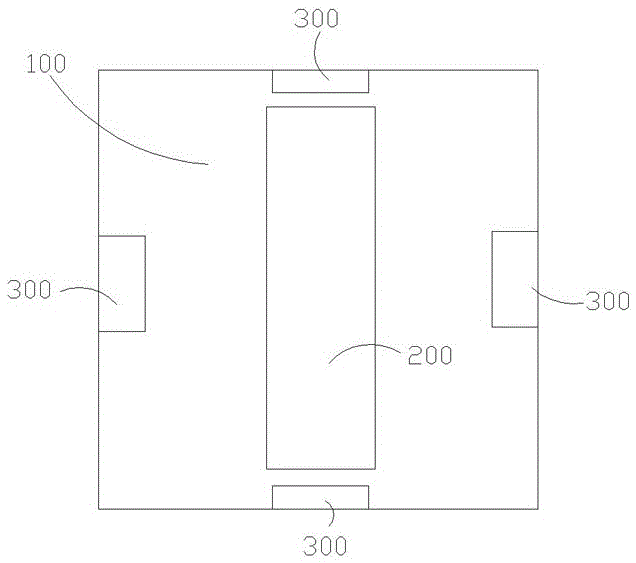
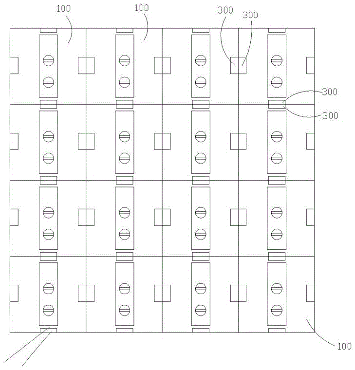
[0029] Such as Figures 1 to 8 As shown, a power signal lock body integrated connector includes several connection lock bodies 300 , and the several connection lock bodies 300 are sequentially arranged on the outer surface of the box body 100 .

[0030] In a specific implementation, the cabinet 100 is a cabinet of a display screen, such as a cabinet of an LED display screen.

[0031] Such as figure 1 , 2 As shown, in a specific implementation, four connection locking bodies 300 may be respectively arranged on the upper, lower, left and right outer surfaces of the box body 100 .

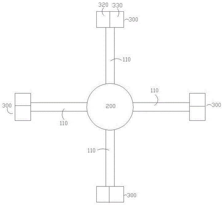
[0032] Such as image 3 As shown, each of the connecting locking bodies 300 is connected to the screen power supply signal module 200 through an internal circuit 110 , and the internal circuit 110 is arranged in the box body 100 .

[0033] The connection locking body 300 is used to determine the connection relationship between any adjacent display screens, and at the same time, the connection lock...


PUM


Abstract

The invention relates to an integrated connector for power supply transmission lines, signal transmission lines and lock bodies and an integrating method. The connector comprises a plurality of connecting lock bodies, wherein each connecting lock body is connected with a screen power signal module through an internal line; the connecting lock bodies are used for determining the connection relationship between any adjacent display screens; meanwhile, the connecting lock bodies are also used for transmitting signals and currents between any adjacent display screens; the connecting lock bodies are divided into plug bodies and socket bodies; each plug body comprises a locking unit and a plug unit; an action unit drives each locking unit to finish a connecting lock action between any adjacent display screens; and the action unit can also drive each plug unit to finish signal and current connection actions between any adjacent display screens.

Description

technical field [0001] The invention relates to a connector between screens and an integration method of the connector, in particular to an integrated connector and an integration method that integrates a power transmission line, a signal transmission line and a connecting lock body between screens into a whole. Background technique [0002] As we all know, with the development of display and imaging technology, various display screens have been widely used in people's living and working environments. Generally speaking, outdoor or large-scale display screens generally require several display screens The screens are spliced ​​together to form a large display screen to achieve the function of infinitely expanding the size of the display screen and displaying large-scale graphic information. This method of use is especially widely used in the field of outdoor advertising screens. [0003] As mentioned above, in order to be able to splice the traditional display screens togethe...

Claims


Application Information

Patent Timeline
Patent Type & Authority Applications(China)
IPC IPC(8): H01R13/629H01R13/627H01R24/00H01R43/26
CPCH01R13/62977H01R13/6275H01R24/00H01R43/26
Inventor 朱建平刘剑冰杨云灿
Owner 刘剑冰
Learn More