Clamping frame for vertically storing thin plates

A clamping frame and thin plate technology, which is applied in the field of thin plate clamping and storage equipment, can solve the problems of not being suitable for modern production, occupying a large space, and thin plate parts are prone to rust, so as to improve the utilization rate of equipment and avoid occupying a large space Effect

Active Publication Date: 2016-04-27
ANHUI PULUN INTELLIGENT EQUIP CO LTD
View PDF7 Cites 0 Cited by
  • Summary
  • Abstract
  • Description
  • Claims
  • Application Information

AI Technical Summary

Problems solved by technology

[0002] When the thin plate parts are stored, if the environment is difficult to keep fully dry, or the paint surface on the thin plate parts is not completely dried, rust spots are easy to appear on the thin plate parts, or the paint surface on the thin plate parts is scratched due to improper storage of the thin plate parts, usually Store the thin plate parts separately, but the traditional spreading method takes up a lot of space and is not suitable for modern production
In the storage racks stacked along the vertical space, if the equipment is open, dust is easy to accumulate on the thin plate, and the use of relatively closed storage equipment is not conducive to the ventilation of the thin plate storage environment, and it is very difficult to inspect the thin plate. inconvenient

Method used


Image

  • Clamping frame for vertically storing thin plates
  • Clamping frame for vertically storing thin plates
  • Clamping frame for vertically storing thin plates

Examples


Embodiment Construction

[0018] In order to make the technical means and creative features of the present invention easy to understand, the present invention will be further explained below.

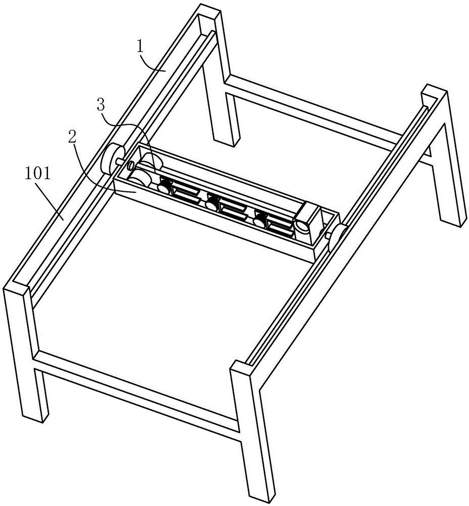
[0019] Such as Figure 1 to Figure 5 As shown, a vertical storage and clamping frame for thin plate parts includes a main frame 1, a sliding frame 2 and a clamping plate frame 3.

[0020] Each of the left and right ends of the main frame 1 is provided with a slideway 101.

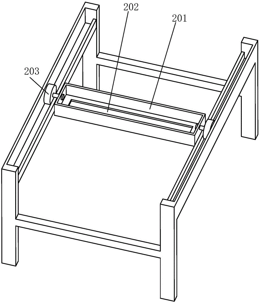
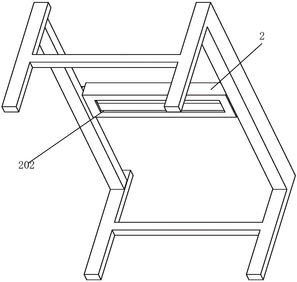
[0021] The upper end surface of the sliding frame 2 is provided with a rectangular groove 201, the center of the lower end surface of the rectangular groove 201 is provided with a horizontal bar-shaped hole 202, and the left end surface and the right end surface of the sliding frame 2 are each installed with one The rollers 203 respectively located in the slideway 101 on the corresponding side can roll back and forth in the slideway 101 on the corresponding side.

[0022] The clamping plate frame 3 includes a vertical plate 4, a side wheel 5 is inst...


PUM


Abstract

The invention relates to a clamping frame for vertically storing thin plates. The clamping frame comprises a main body frame, a sliding frame and a clamping plate frame, wherein a sliding way is formed in each of the left and right ends of the main body frame separately; a rectangular groove is formed in the upper end plane of the sliding frame; a transverse strip-shaped hole is formed in the center of the lower end plane of the rectangular groove; a rolling wheel positioned in the sliding way in the corresponding side is mounted on each of the left end plane and the right end plane of the sliding frame separately; the rolling wheels can roll front and back in the sliding ways in the corresponding sides; the clamping plate frame comprises a vertical plate; a side wheel is mounted at the left end of the vertical plate; the thickness of the side wheel is larger than the width of the strip-shaped hole, and less than the width of the rectangular groove; a limiting block is fixed at the right end of the vertical plate; and a plurality of pressing frames are uniformly arranged on the vertical plate. According to the clamping frame, the thin plates are arranged in a vertical, laminated and suspending manner, so that a large occupied area caused by a conventional unfolded placement way can be avoided, and the problem that the thin plates cannot be detected conveniently when the thin plates are arranged in the vertical and laminated manner can be avoided as well.

Description

Technical field [0001] The invention relates to the technical field of thin-plate parts clamping and storing equipment, in particular to a vertical storage and clamping frame for thin-plate parts. Background technique [0002] When the thin-plate parts are stored, if the environment is difficult to keep fully dry, or the painted surface of the thin-plate parts is not completely air-dried, the thin-plate parts are prone to rust spots, or the paint surface of the thin-plate parts is scratched due to improper storage of the thin-plate parts. The thin plate parts are stored separately, but the traditional spreading method takes up a large space and is not suitable for modern production. In the storage rack stacked along the vertical space, if the equipment is open, it is easy to accumulate dust on the thin plate parts, and the use of relatively closed storage equipment is not conducive to the ventilation of the thin plate storage environment, and the inspection of the thin plate part...

Claims


Application Information

Patent Timeline
IPC IPC(8): A47B81/00
CPCA47B81/00
Inventor 谭铁龙
Owner ANHUI PULUN INTELLIGENT EQUIP CO LTD
Why Eureka
Try Eureka