
Current transformer IGBT power module field double-pulse testing system and method

A technology for power modules and test systems, applied in bipolar transistor testing, single semiconductor device testing, instruments, etc., can solve problems such as inapplicability to on-site testing, large errors, and difficulty in meeting engineering needs, achieving simple testing, eliminating errors, Accurate test results

Inactive Publication Date: 2016-04-20
TONGJI UNIV
View PDF6 Cites 40 Cited by
  • Summary
  • Abstract
  • Description
  • Claims
  • Application Information

AI Technical Summary

Problems solved by technology

However, the system can only be tested in the laboratory and is not suitable for field testing
[0005] In the article "Design of High Efficiency Converter for High Power Direct Drive Wind Power System" published by the Chinese Journal of Electrical Engineering in 2010, a method combining circuit time domain simulation and device loss curve to calculate converter loss is proposed. This method does not require additional devices , but because there is a certain difference between the device loss curve and the actual operating situation, the error of this method is large, and it is difficult to meet the engineering requirements
The device can automatically collect, transmit and process the data obtained from the double-pulse test to obtain the dynamic characteristics of the IGBT, but this method is not suitable for on-site testing

Method used


Image

  • Current transformer IGBT power module field double-pulse testing system and method
  • Current transformer IGBT power module field double-pulse testing system and method
  • Current transformer IGBT power module field double-pulse testing system and method

Examples


Embodiment Construction

[0049] The present invention will be described in detail below in conjunction with the accompanying drawings and specific embodiments.

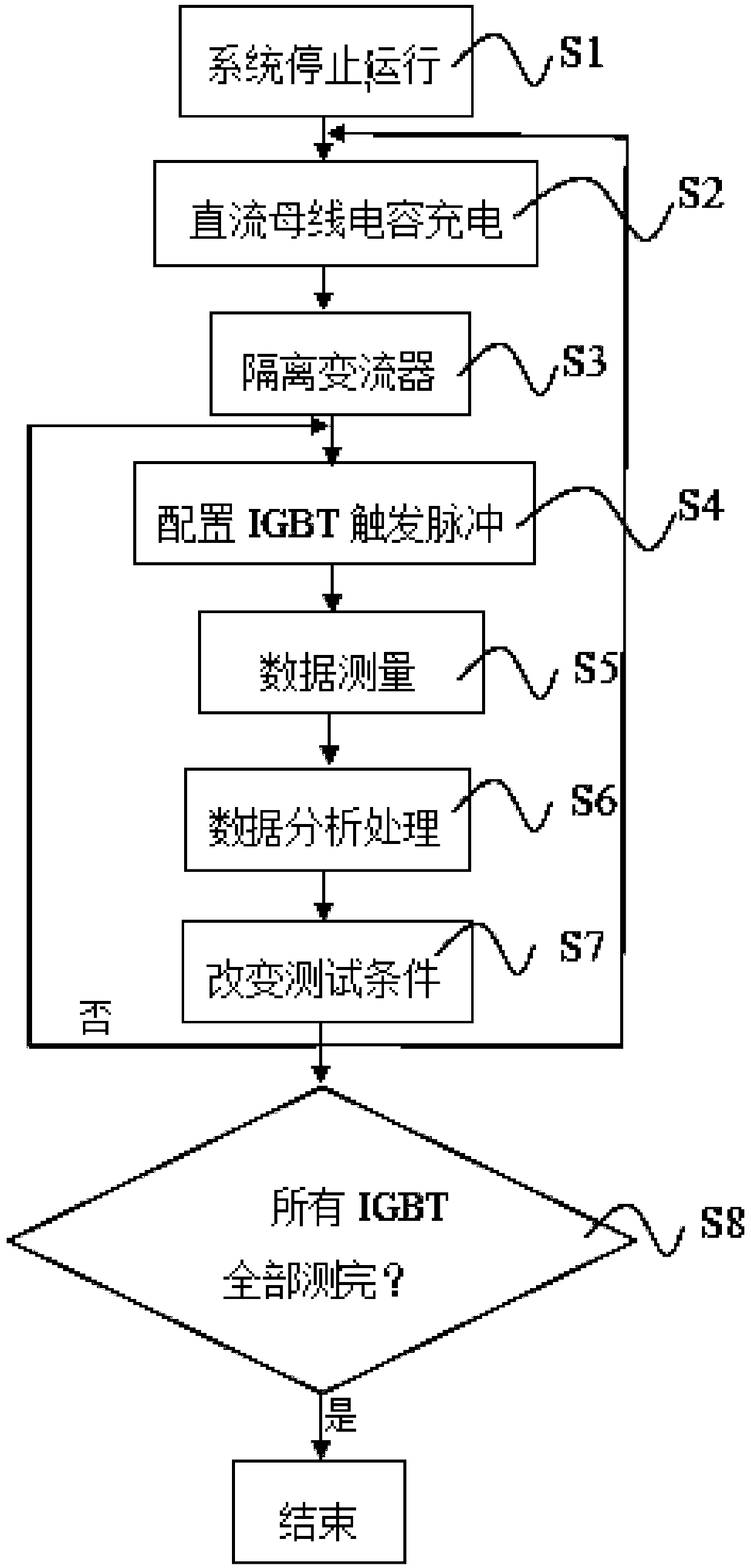
[0050] Such as figure 1 - As shown in -2, a field double-pulse test system for the IGBT power module of a converter is used to test the characteristics of the IGBT power module 3 in the converter on site, including

[0051] Double-pulse test circuit: including input power supply 1, converter and load connected in sequence, the input power supply 1 is the input power actually used in the system using the converter, and the load is the system using the converter The actual motor used in 4,

[0052] Detection unit: used to detect relevant parameters of each IGBT in the IGBT power module 3 in the converter,

[0053] Data acquisition unit: connected to the detection unit, used to collect the measured IGBT related parameters,

[0054] Data processing unit: connected with the data acquisition unit, used to analyze and process the measured IGBT re...


PUM


Abstract

The present invention relates to a current transformer IGBT power module field double-pulse testing system and a method. The testing system comprises a double-pulse testing circuit which comprises a double-pulse testing circuit which comprises an input power supply (1), a current transformer and a load which are connected in order, a detection unit which is used for detecting the relevant parameters of each IGBT in the IGBT power module (3) in the current transformer, a data acquisition unit which is connected to the detection unit and is used for collecting the measured relevant parameters of the IGBT, and a data processing unit which is connected to the data acquisition unit and is used for carrying out analyzing processing on the measured relevant parameters of the IGBT. The testing method comprises the steps of (1) constructing a double-pulse testing circuit, (2) carrying out data measurement to measure the switch parameter of each IGBT in the IGBT power module (3) in the current transformer, and (3) carrying out data processing to carrying out analyzing processing on the measured switch parameter of the IGBT. Compared with the prior art, the system and the method have the advantages of accurate measurement and convenient measurement and are suitable for field measurement.

Description

technical field [0001] The invention relates to a converter IGBT power mode test system and method, in particular to a converter IGBT power module on-site double-pulse test system and method. Background technique [0002] In recent years, IGBT power modules have been widely used in electric drives and new energy power generation systems, such as electric vehicles, subways, high-speed rails, and wind power. The invention proposes a double-pulse test system and method for an IGBT power module in a converter to facilitate on-site measurement of IGBT switch characteristics, which is of great significance for ensuring safe, efficient and reliable operation of the converter. On the one hand, in the design and development stage of the converter, on-site measurement of the switching characteristics of the IGBT power module in the converter can provide a basis for gate drive and main circuit optimization (such as gate resistance value selection, DC busbar layout, etc.). For example,...

Claims


Application Information

Patent Timeline
Patent Type & Authority Applications(China)
IPC IPC(8): G01R31/26
CPCG01R31/2608G01R31/2617
Inventor 向大为刘也可袁逸超
Owner TONGJI UNIV
Learn More