
Grain conveying chain structure

A conveyor chain and grain technology, applied in the field of grain conveyor chain structure, can solve problems such as increasing the workload of equipment maintenance, reducing the amount of material conveyed, and cleaning complicated locks, so as to improve equipment operation efficiency, reduce its own weight, and reduce equipment maintenance workload effect

Inactive Publication Date: 2016-04-20
仪征市福斯特机械制造有限责任公司
View PDF0 Cites 1 Cited by
  • Summary
  • Abstract
  • Description
  • Claims
  • Application Information

AI Technical Summary

Problems solved by technology

Due to the ribbed shape of the traditional rectangular ribs, the materials are often brought back during the continuous transportation of materials, and the more materials are brought back, the more the materials are brought back, which reduces the amount of materials conveyed, and it is cumbersome and difficult to clean up after accumulation, which increases the The maintenance workload of equipment affects the normal operation of production

Method used


Image

  • Grain conveying chain structure

Examples


Embodiment Construction

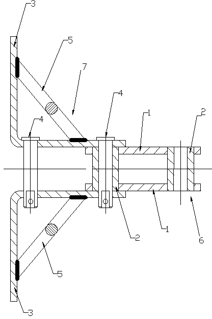
[0007] Such as figure 1 As shown, the present invention includes an inner chain link group 6 and an outer chain link group 7 which are alternately connected. The inner chain link group 9 includes two inner chain plates 1, and both ends of the two inner chain plates 1 are respectively provided with circular channels. The two inner chain plates 1 are provided with spacers 2 in the circular through holes at both ends of the interference fit.

[0008] The outer chain link group 7 includes two L-shaped outer chain plates 3; the two outer chain plates 3 of the outer chain link group 7 are symmetrically arranged on both sides of the inner chain link group, and the two outer chain plates of the outer chain link group 7 3 and the spacer 2 of the inner connection group are connected by a pin 4.

[0009] The inner sides of the two outer chain plates 3 of the outer chain link group 7 are respectively welded with reinforcing ribs 5, and the reinforcing ribs 5 are cylindrical.


PUM


Abstract

The invention provides a grain conveying chain structure and relates to the field of conveying equipment. The grain conveying chain structure comprises inner chain link groups and outer chain link groups, which are alternately connected; each inner chain link group comprises two inner chain plates, wherein circular through holes are formed in two ends of the two inner chain plates, respectively, and spacer bushes are arranged in interference fit in the circular through holes in the two ends of the two inner chain plates; each outer chain link group comprises two L-shaped outer chain plates; the two outer chain plates of each outer chain group are symmetrically arranged on two sides of each inner chain link group, and the two outer chain plates of each outer chain link group are connected with the spacer bushes of each inner chain link group by means of pin shafts; stiffeners, which are cylindrical, are welded on inner sides of the two outer chain plates of all the outer chain link groups, respectively. The grain conveying chain structure has the advantage that the cylindrical stiffeners are adopted to reduce the phenomenon of bringing back materials in a material transportation process and increase the amount of transportation.

Description

Technical field [0001] The invention relates to the field of conveying equipment, in particular to a grain conveying chain structure. Background technique [0002] In the transportation of food machinery, the scraper chain used for conveying is in a closed shell. The moving scraper conveyor chain continuously conveys powdery, granular grains and other bulk materials. During transportation, the scraper chain is buried in the material being transported. In order to increase the stability of the structure, the 90° bend outer chain plate in the outer chain link needs to be added with a stiffener. The position of the stiffener is also affected by the structure. Considering that, generally placed on the non-contact surface of the material, the traditional shape of the stiffener is a rectangle, and then the stiffener is welded on the inner side of the 90° bend outer chain plate by welding technology. The traditional rectangular reinforcing ribs often return the materials during the con...

Claims


Application Information

Patent Timeline
IPC IPC(8): B65G19/20
Inventor 童华松
Owner 仪征市福斯特机械制造有限责任公司
Learn More