Broadband Directional Antenna Based on Resonant Reflector

A technology of directional antenna and broadband antenna, which is applied in the direction of antenna, antenna grounding switch structure connection, radiation element structure, etc., can solve the problems of limited application range, complex design, and narrow bandwidth of microstrip antenna impedance, so as to save system resources, The effect of compact antenna structure and high optimization efficiency

Inactive Publication Date: 2018-01-09
BEIJING SIMULATION CENT
View PDF9 Cites 0 Cited by
  • Summary
  • Abstract
  • Description
  • Claims
  • Application Information

AI Technical Summary

Problems solved by technology

The above-mentioned antennas have high directivity, but unfortunately, they all have their own shortcomings: the microstrip antenna can achieve good directivity because the metal layer is covered on the other side of the dielectric substrate as the floor, but the metal layer The existence of the microstrip antenna leads to a very narrow impedance bandwidth, usually only about 5%; the Yagi antenna usually has a forward gain of more than 10dBi, but its inherent narrow frequency band and end-fire characteristics limit its application range; logarithmic period Antennas and Vivaldi antennas are frequency-invariant antennas. They have a wide impedance bandwidth and can maintain relatively stable directivity throughout the passband. However, their large size and end-fire characteristics make them suitable for portable applications. No advantages at all; parabolic and horn antennas are also limited in scope due to their relatively large size
Although the above studies have produced a certain degree of orientation through certain methods, their front-to-back ratios are not particularly high, and all these methods are slightly complicated in design
This increases the design cost and is not applicable in some occasions
In addition, these patents cannot meet the requirements of low-profile and miniaturized antennas

Method used


Image

  • Broadband Directional Antenna Based on Resonant Reflector
  • Broadband Directional Antenna Based on Resonant Reflector
  • Broadband Directional Antenna Based on Resonant Reflector

Examples


Embodiment Construction

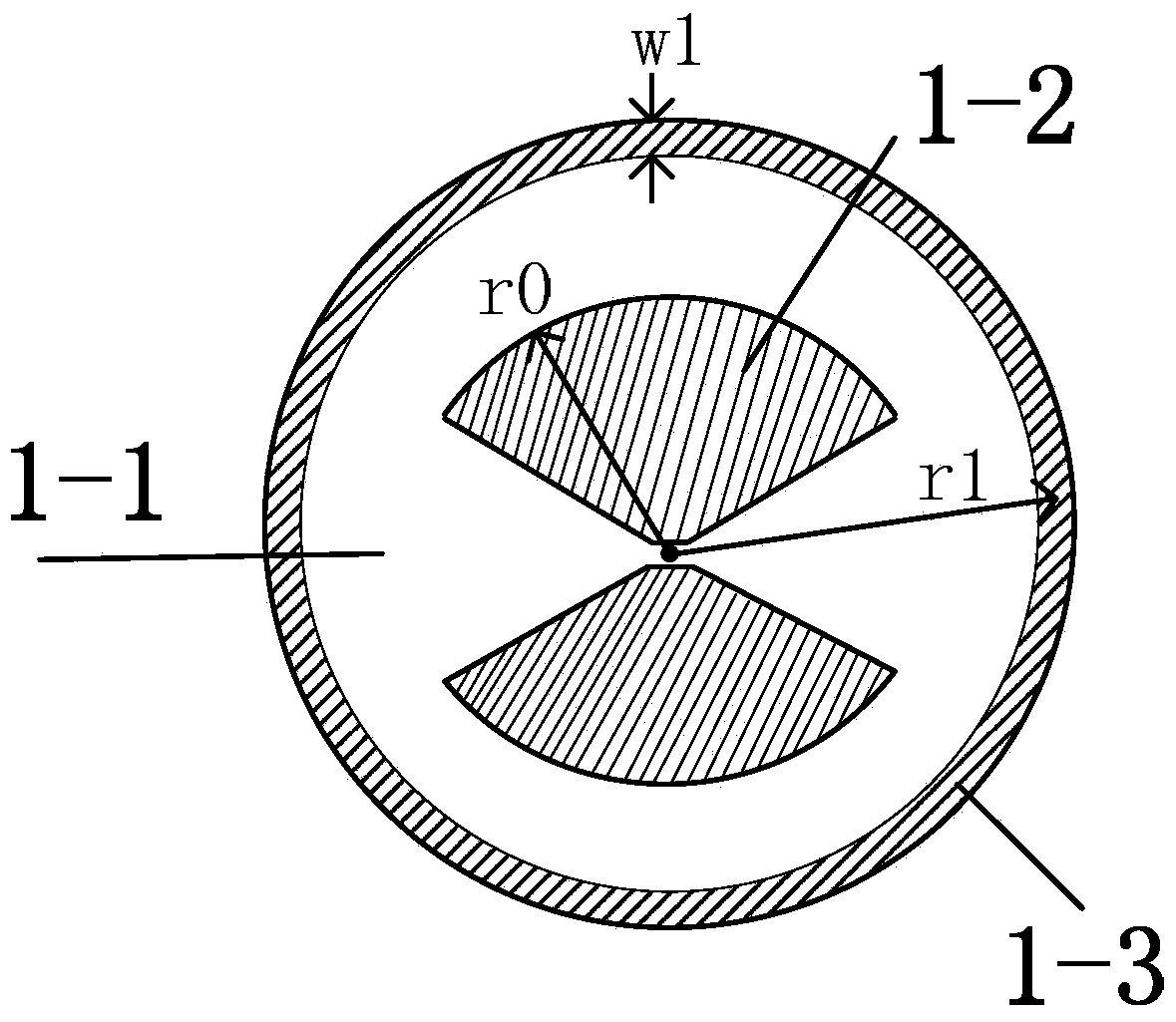
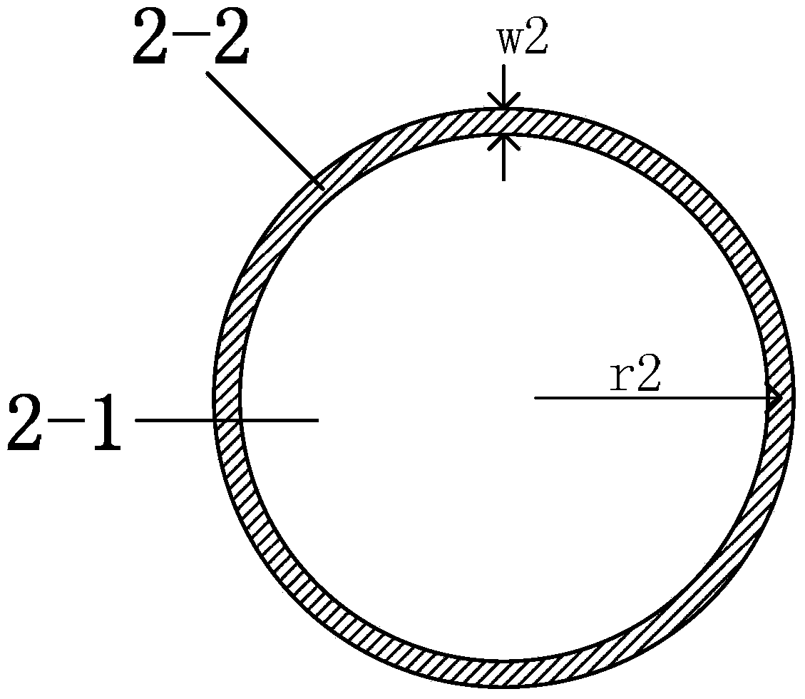
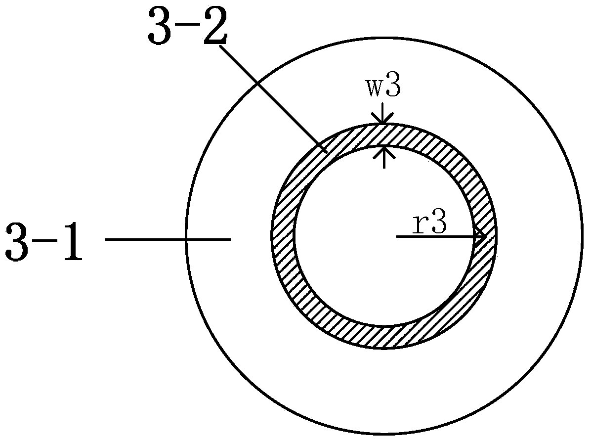
[0034] A broadband directional antenna based on a resonant reflector, such as Figure 1-4As shown, the antenna has 3 layers, from top to bottom are the director layer 3, the broadband antenna body layer 1 and the resonant reflector layer 2, that is, the resonant reflector layer 2 is located directly below the broadband antenna body layer 1 ; The director layer 3 is located directly above the broadband antenna body layer 1 . In a preferred embodiment of the present invention, the director layer 3, the broadband antenna body layer 1 and the resonant reflector layer 2 are supported by plastic rods. The distance between the resonant reflector layer 2 and the broadband antenna body layer 1 is greater than the distance between the director layer 3 and the broadband antenna body layer 1 . The reflection phase of the resonant reflector layer 2 is less than 180° of the traditional metal reflector (PEC), and is approximately between 90° and 150°. Therefore, the distance between the re...


PUM


Abstract

The invention discloses a broadband directional antenna based on a resonant reflector. The broadband directional antenna is mainly composed of a broadband antenna body layer, a resonant reflector layer and a director layer. The resonant reflector layer is arranged exactly below the broadband antenna body layer. The director layer is arranged exactly above the broadband antenna body layer. The broadband antenna body layer comprises a body dielectric substrate, and a main radiation patch and a metal loading ring which are adhered on the body dielectric substrate. The resonant reflector layer comprises a resonant dielectric substrate and a metal resonant ring which is adhered on the resonant dielectric substrate. The director layer comprises a directing dielectric substrate and a metal directing ring which is adhered on the directing dielectric substrate. A higher profile required by loading of a conventional metal reflecting board on the antenna is overcome, and larger area and narrower frequency band required by loading of an AMC structure on the antenna is also overcome so that the broadband directional antenna based on the resonant reflector has dual advantages.

Description

technical field [0001] The invention relates to the field of broadband antennas and directional antennas, in particular to a broadband directional antenna based on a resonant reflector. Background technique [0002] With the progress of society and technology, wireless communication technology has been developed rapidly, and the bandwidth of signals is also continuously improved. Ultra-Wideband (Ultra-Wideband) antennas, as the core components in broadband communication systems, have also been greatly developed. However, UWB antennas have some general disadvantages, such as having to sacrifice gain in order to increase bandwidth; and the pattern will deteriorate at high frequencies, and so on. These shortcomings seriously affect the communication quality. Moreover, ultra-wideband antennas usually radiate omnidirectionally or bidirectionally. With more and more antennas on modern carrier systems, electromagnetic compatibility is a big problem; in fields that require high co...

Claims


Application Information

Patent Timeline
Patent Type & Authority Patents(China)
IPC IPC(8): H01Q1/38H01Q15/14H01Q19/10H01Q1/50
CPCH01Q1/38H01Q1/50H01Q15/14H01Q19/10
Inventor 彭麟谢继杨孙凯姜兴仇玉杰
Owner BEIJING SIMULATION CENT
Why Eureka
Try Eureka