Rope gripper
A rope clamp and clamp block technology, applied in the field of rope clamps, can solve the problem that the safety brake cannot meet the actual use needs of elevator safety protection, achieve reliable and fast clamping and braking, realize safe braking, and avoid upward rushing to the top. or the effect of rolling down the car
- Summary
- Abstract
- Description
- Claims
- Application Information
AI Technical Summary
Problems solved by technology
Method used
Image
Examples
Embodiment 1
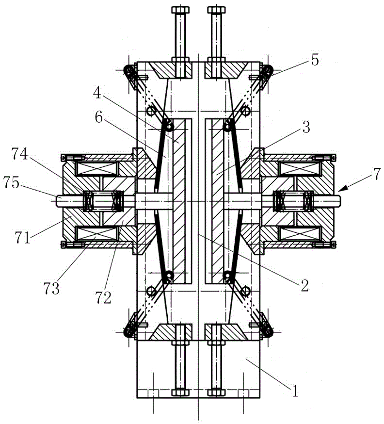
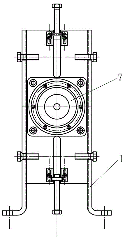
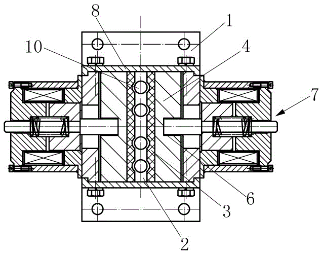
[0035] Such as figure 1 , figure 2 , image 3As shown, the frame 1 is a three-dimensional frame structure in the shape of a square column, and upper and lower opposite slit openings are arranged on the top surface and the bottom surface of the frame 1, and two brake clips with opposite clamping surfaces are arranged in the frame 1, A rope channel 2 is formed between the clamping surfaces of the two brake clips, and the rope channel 2 is vertically opposite to the slit-shaped opening on the frame 1 , so that the traction wire rope 10 can pass up and down in the frame 1 . The two brake clips are arranged opposite to each other, and the opposite surfaces of the brake clips are clamping surfaces parallel to each other, and a friction plate 3 is arranged on the clamping surface of each brake clip. The two brake clips in this embodiment are both movable clips 4 , and the two movable clips 4 have the same structure and are arranged symmetrically in the frame 1 .
[0036] figure ...
Embodiment 2
[0047] The structure of this embodiment is basically the same as that of Embodiment 1, and it is also the setting structure of double movable clamping blocks, and is provided with two brake trigger mechanisms; the front ends of the brake push rods 75 in the two brake trigger mechanisms respectively push Trigger braking is performed in the chute 6 of the movable clamp block 4 on each side.
[0048] The difference is that the rope channel 2 is an upper and lower channel that is surrounded by three sides and opened on one side by the frame 1, the brake clip and the end plate 8 ( Figure 5 ). The open side of the rope channel is convenient for installing the rope clamp on the elevator equipment that is not easy to disassemble, that is, the steel wire rope 10 on the elevator can enter the rope channel 2 through the open side, thus greatly facilitating the installation of the rope clamp .
Embodiment 3
[0050] Such as Figure 6 As shown, the structure of this embodiment is basically the same as that of Embodiment 1, except that one of the two brake clips in the frame 1 is a movable clip 4, and the other is a fixed clip 9; the fixed clip 9 is fixed on the frame 1, and save the setting of a corresponding brake trigger mechanism. Therefore, in this embodiment, only the frame 1 on one side of the movable clamp block 4 is provided with a brake trigger mechanism, and the brake trigger mechanism includes a brake electromagnet 7, a compression spring 74, a brake push rod 75, and the like. Similarly, the braking electromagnet 7 is composed of a yoke 71, an armature 72 and an electromagnetic coil 73; the compression spring 74 is installed in the inner cavity of the braking electromagnet 7 (it can also be arranged outside the braking electromagnet) , the brake push rod 75 passes through the yoke 71 , the armature 72 and the compression spring 74 , and maintains a linkage structure with...
PUM
 Abstract
Description
Claims
Application Information
 - R&D
- Intellectual Property
- Life Sciences
- Materials
- Tech Scout
- Unparalleled Data Quality
- Higher Quality Content
- 60% Fewer Hallucinations
Browse by: Latest US Patents, China's latest patents, Technical Efficacy Thesaurus, Application Domain, Technology Topic, Popular Technical Reports.
© 2025 PatSnap. All rights reserved.Legal|Privacy policy|Modern Slavery Act Transparency Statement|Sitemap|About US| Contact US: help@patsnap.com


