Fixing and adjusting device for screen frame for screen printing and method of using the same
An adjusting device and screen printing technology, which are applied in screen printing, printing, printing and other directions, can solve the problems of low accuracy, narrow adjustment range, single adjustment effect, etc., and achieve good adjustment effect, wide adjustment range, The effect of a wide range of applications
- Summary
- Abstract
- Description
- Claims
- Application Information
AI Technical Summary
Problems solved by technology
Method used
Image
Examples
Embodiment 1
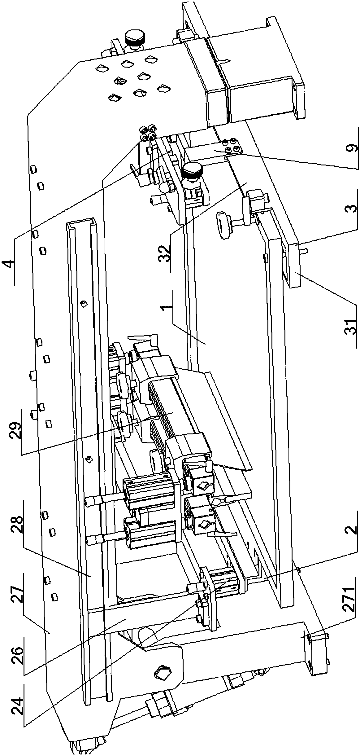
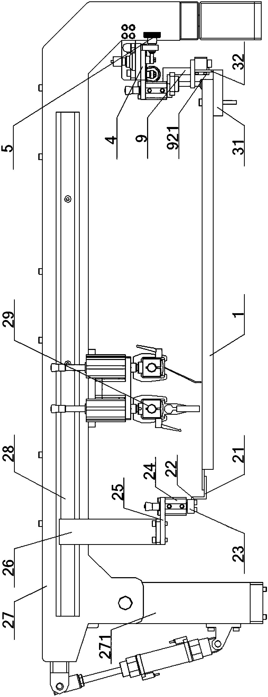
[0078] See figure 1 - Picture 11 , A device for fixing and adjusting a screen frame for screen printing, comprising a screen frame 1, a left screen frame bracket 2 and a right screen frame bracket 3. The left and right ends of the screen frame 1 are respectively connected to the left screen frame bracket 2 , The right screen frame bracket 3 is connected, and a screen frame adjustment device 4 is connected to the right screen frame bracket 3;
[0079] The bottoms of the left and right ends of the screen frame 1 are respectively locked and connected with the bottoms of the left screen frame bracket 2 and the right screen frame bracket 3 located directly below, and the tops of the left screen frame bracket 2 and the right screen frame bracket 3 are higher than The screen frame 1 is set, the top of the left screen frame bracket 2 is connected with the lifting device 24, and the top of the right screen frame bracket 3 is connected with the screen frame adjusting device 4;
[0080] The...
Embodiment 2
[0089] The basic content is the same as Example 1, the difference is:
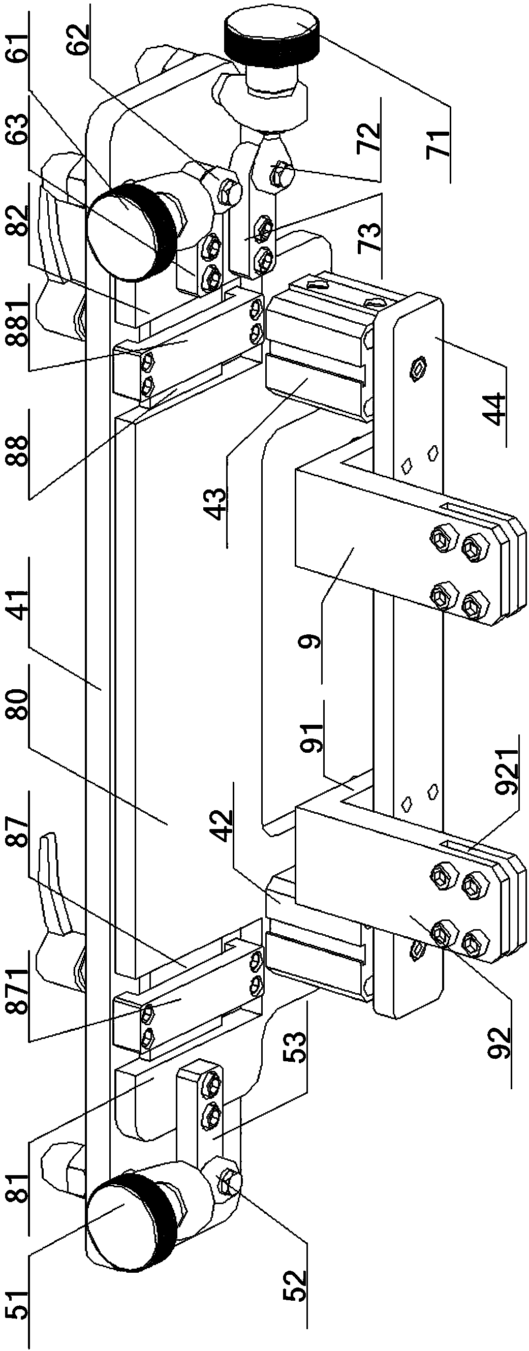
[0090] The No. 1 front-to-rear adjustment device 5 is arranged near the open end of the No. 1 cavity 85, which includes a No. 1 fine-tuning knob 51, a No. 1 fisheye joint 52 and a No. 1 fine-tuning straight plate 53, the top of the No. 1 fine-tuning knob 51 Connected to the bottom surface of the fixing plate 41, the output end of the No. 1 fine adjustment knob 51 is connected to one end of the No. 1 fisheye connector 52, and the other end of the No. 1 fisheye joint 52 is hingedly connected with one end of the No. 1 straightening plate 53, The other end of the No. 1 fine adjustment straight plate 53 is connected to the bottom of the No. 1 end plate 81, and the central axis of the No. 1 fine adjustment knob 51 and the No. 1 fisheye joint 52 is perpendicular to the central axis of the No. 1 fine adjustment straight plate 53.
[0091] The number one front and rear adjustment device 5 pulls the special-shaped slide ...
Embodiment 3
[0093] The basic content is the same as Example 1, the difference is:
[0094] The No. 2 front-to-rear adjustment device 6 is arranged near the open end of the No. 2 cavity 86, which includes a No. 2 fine-tuning knob 61, a No. 2 fisheye joint 62, and a No. 2 fine-tuning straight plate 63. The top of the No. 2 fine-tuning knob 61 Connected to the bottom surface of the fixed plate 41, the output end of the No. 2 fine-tuning knob 61 is connected to one end of the No. 2 fish-eye connector 62, and the other end of the No. 2 fish-eye joint 62 is hingedly connected to one end of the No. 2 straight-adjusting plate 63, The other end of the second trimming straight plate 63 is connected to the bottom of the second end plate 82, and the central axis of the second trimming knob 61 and the second fisheye joint 62 is perpendicular to the central axis of the second trimming straight plate 63.
[0095] The No. 2 front and rear adjustment device 6 pulls the special-shaped sliding plate 8 through th...
PUM
 Abstract
Description
Claims
Application Information
 - R&D
- Intellectual Property
- Life Sciences
- Materials
- Tech Scout
- Unparalleled Data Quality
- Higher Quality Content
- 60% Fewer Hallucinations
Browse by: Latest US Patents, China's latest patents, Technical Efficacy Thesaurus, Application Domain, Technology Topic, Popular Technical Reports.
© 2025 PatSnap. All rights reserved.Legal|Privacy policy|Modern Slavery Act Transparency Statement|Sitemap|About US| Contact US: help@patsnap.com


