
A DC current limiter

A current limiter, DC circuit technology, applied in electrical components, emergency protection circuit devices, circuit devices, etc., can solve the problems of decreased insulation level, increased mechanical stress, no solution, etc., to improve continuity and improve speed. sexual effect

Inactive Publication Date: 2018-12-28
HUAZHONG UNIV OF SCI & TECH
View PDF5 Cites 0 Cited by
  • Summary
  • Abstract
  • Description
  • Claims
  • Application Information

AI Technical Summary

Problems solved by technology

In some cases, the quench recovery time is as long as several seconds, which cannot meet the requirements of the DC power supply system;
[0006] (2) Problems such as heat generation, overvoltage, insulation level drop, increased mechanical stress, and rapid expansion of cooling medium after quench have no good solutions so far;
[0008] Since the above problems cannot be solved, the resistive superconducting DC current limiter still cannot be widely used at present.

Method used


Image

  • A DC current limiter
  • A DC current limiter
  • A DC current limiter

Examples


Embodiment Construction

[0038] In order to make the object, technical solution and advantages of the present invention clearer, the present invention will be further described in detail below in conjunction with the accompanying drawings and embodiments. It should be understood that the specific embodiments described here are only used to explain the present invention, not to limit the present invention.

[0039] Compared with the AC transmission system, the fault development speed of the DC power supply system is faster, and the response speed of the line protection is higher, so the control and protection are more difficult.

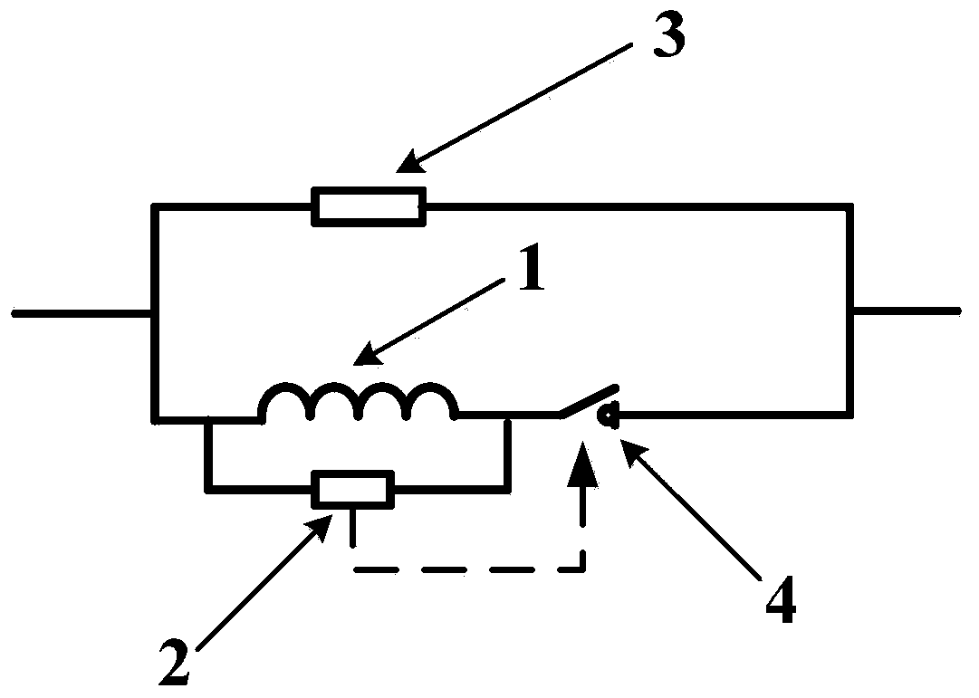
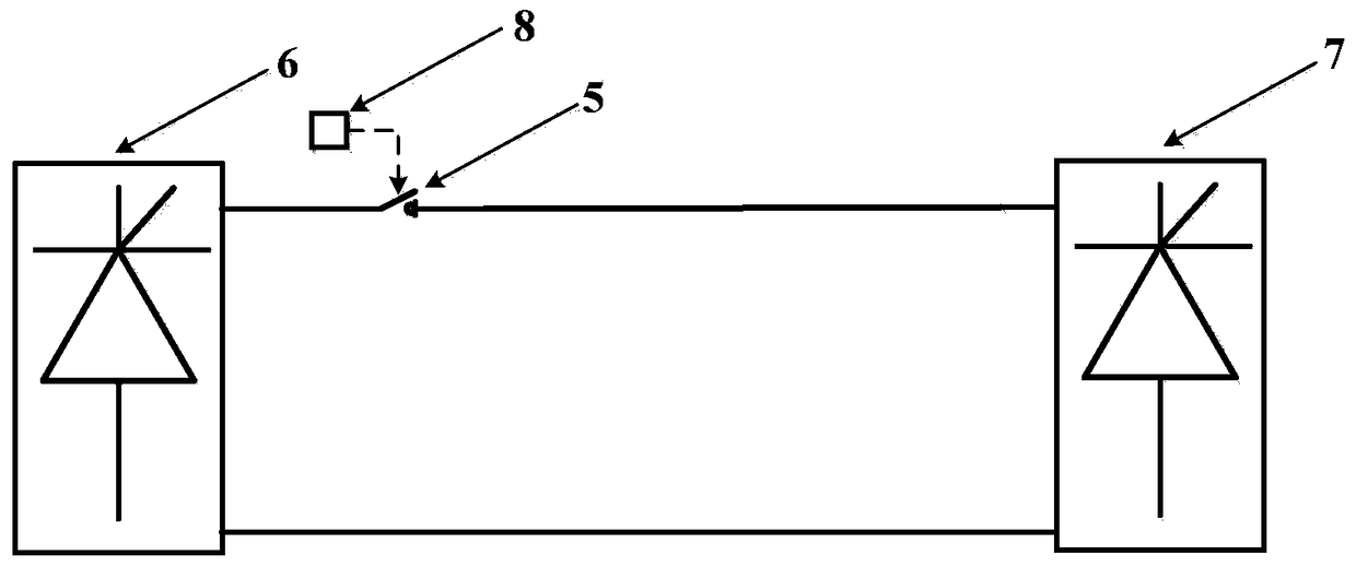
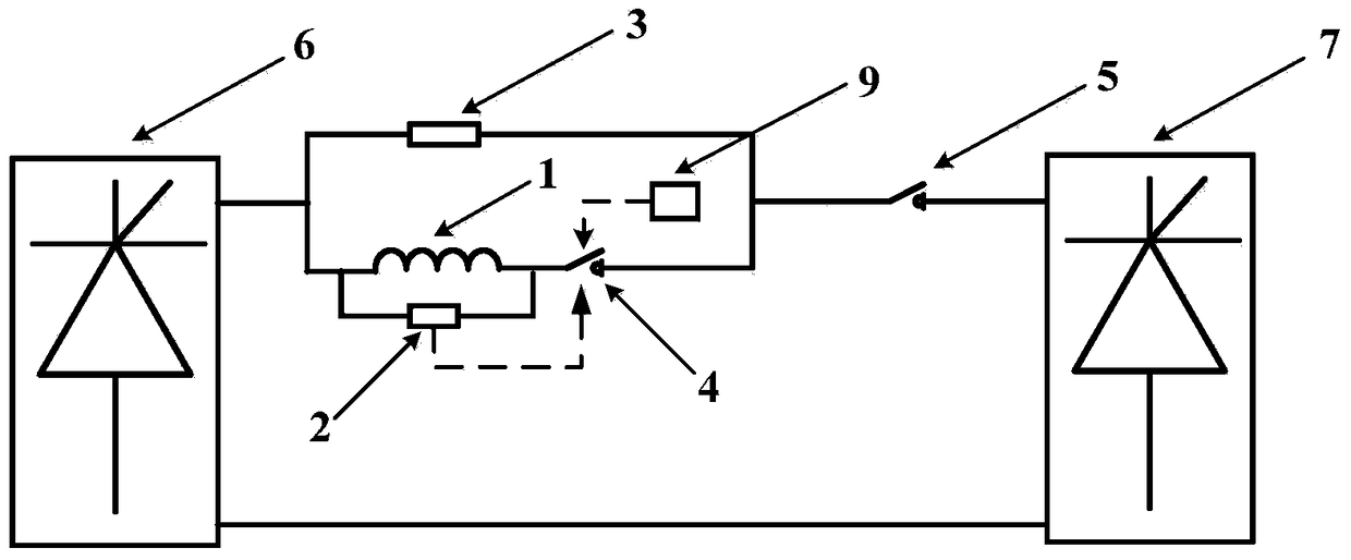
[0040] In the present invention, a novel DC current limiter is formed by using a current-limiting inductance (conventional inductance or superconducting coil can be used), a current-limiting resistor, a parallel resistor and a current-limiter branch circuit breaker (power electronic switching devices can be used). This new type of DC current limiter uses the characteristics o...


PUM


Abstract

The present invention discloses a novel direct current limiter which comprises a current limiting inductor, a current limiting resistor, a parallel resistor and a current limiter branch circuit breaker. When a direct current transmission line is normally operated, the current limiting inductor can be used as a smoothing reactor. When the direct current transmission line has a short-circuit fault, the direct current limiter will limit an increase speed of a short-circuit current. When a value of the short-circuit current exceeds a security threshold value, the current limiting resistor is connected into the transmission line so as to reduce the amplitude of the short-circuit current; then re-closing is carried out, and if re-closing succeeds, the branch circuit breaker is re-closed; and if re-closing does not succeed, the branch circuit breaker is disconnected, and the fault line stops so as to prevent the short-circuit fault from causing adverse affects on other electric power apparatus, power supply system and the like. The present invention also discloses a value-taking rule of parameters of various modules in the current limiter in order to enable the novel direct current limiter to achieve an optimal operation effect in actual practice.

Description

technical field [0001] The invention belongs to the technical field of short-circuit current limiting protection of a DC power supply system, and more specifically relates to a DC current limiter. Background technique [0002] Due to the characteristics of the reverse distribution of primary energy and load demand in my country, it is objectively required to optimize the allocation of energy in a wide range. Due to its technical advantages, high-voltage direct current transmission technology has become an important means to solve long-distance cross-regional power transmission. Following the power transmission projects in the Three Gorges area and the west-to-east power transmission projects, power transmission projects such as Fufeng UHV DC and Debao DC have been put into operation one after another, and several UHV DC power transmission projects have entered the planning and design stage. [0003] However, due to the relatively low damping of the DC power supply system, c...

Claims


Application Information

Patent Timeline
Patent Type & Authority Patents(China)
IPC IPC(8): H02H3/02
CPCH02H3/025
Inventor 唐跃进张立晖刘洋任丽石晶周奥波周晓龚康
Owner HUAZHONG UNIV OF SCI & TECH
Learn More