
A kind of reaction support structure

A technology of reaction force support and frame structure, applied in instruments, measuring devices, scientific instruments, etc., can solve the problems of difficult to meet the test conditions of the actuator and no lifting function.

Active Publication Date: 2019-01-18
BEIJING AUTOMOBILE RES GENERAL INST
View PDF7 Cites 0 Cited by
  • Summary
  • Abstract
  • Description
  • Claims
  • Application Information

AI Technical Summary

Problems solved by technology

[0004] The object of the present invention is to provide a reaction force support structure to solve the problem that the existing actuator reaction force support structure does not have a lifting function and is difficult to meet the test conditions of different angles of the actuator

Method used


Image

  • A kind of reaction support structure
  • A kind of reaction support structure

Examples


Embodiment Construction

[0034] In order to make the technical problems, technical solutions and advantages to be solved by the present invention clearer, the following will describe in detail with reference to specific embodiments and accompanying drawings.

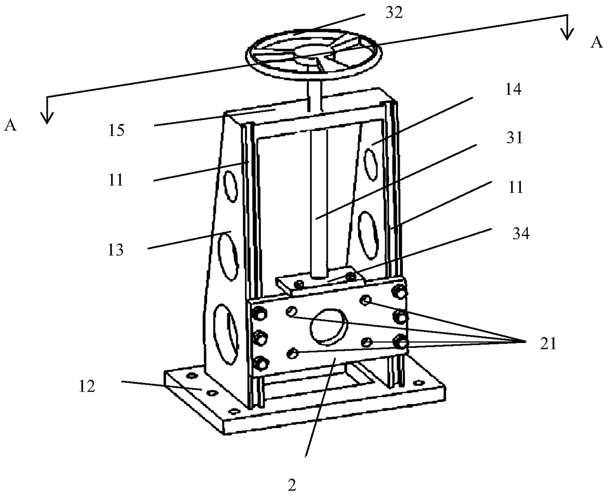
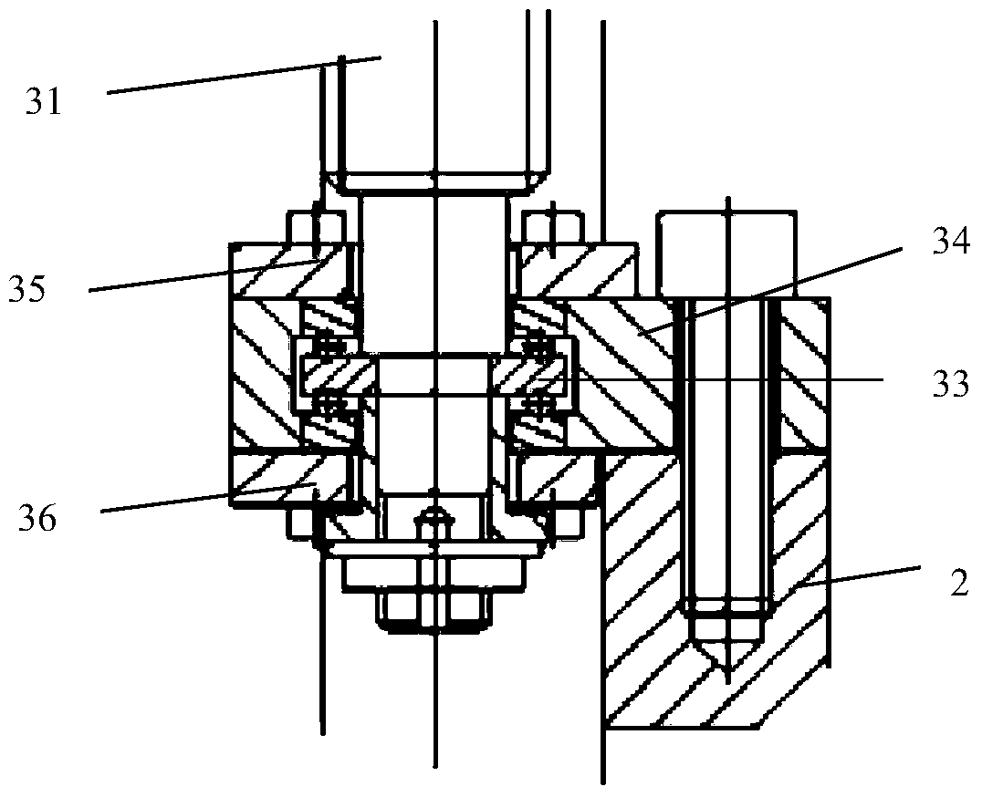
[0035] In the embodiment of the present invention, the existing actuator reaction force support structure does not have a lifting function, and it is difficult to meet the test conditions of different angles of the actuator. Embodiments of the present invention provide a counterforce support structure, such as figure 1 and figure 2 As shown, it includes: a frame structure, a connecting plate and a lifting drive structure, wherein the frame structure is provided with a chute 11; the connecting plate 2 is fixedly connected with the actuator, and the connecting plate 2 is connected to the chute through the chute. The connection of the frame structure includes a first state of being fixed relative to the frame and a second state of moving relative...


PUM


Abstract

The invention provides a counterforce support structure which aims at solving the problem that because an existing actuator counterforce support structure does not have the lifting function, the test conditions of different angles of an actuator can hardly be met. The counterforce support structure comprises a frame structure, a connection plate and a lifting drive structure. Slide grooves are formed in the frame structure. The connection plate is fixedly connected with the actuator and is connected with the frame structure through the slide grooves. The connection plate has the first state in which the connection plate is fixed relative to the frame structure, and the second state in which the connection plate is movable relative to the frame structure. The lifting drive structure is connected with the frame structure and the connection plate. When the connection plate is in the second state, the lifting drive structure drives the connection plate to move along the slide grooves. By means of the counterforce support structure, the problem that an existing actuator counterforce support does not have the lifting function is solved, and therefore it is ensured that the actuator can be adjusted to different heights, and test strips, at different angles, of the actuator are met.

Description

technical field [0001] The invention relates to the technical field of actuator reaction force support design, in particular to a reaction force support structure. Background technique [0002] Along with the process of China's modernization, actuator equipment has been widely used in China, especially in the construction machinery industry. The principle of this actuator is that one end is fixed on the reaction force bracket, and the other end is connected to the test object. , through electricity, gas, liquid and mixed energy as power, load is applied to the test object, and its stiffness and durability are tested, which has achieved the assessment and verification of the test object. [0003] The design of the reaction support needs to have the following capabilities: 1. It has a certain rigidity to ensure that the support cannot be deformed during the process of applying the load to the actuator; 2. It has the function of lifting and lowering to ensure that the actuator ...

Claims


Application Information

Patent Timeline
Patent Type & Authority Patents(China)
IPC IPC(8): G01N3/02
CPCG01N3/02
Inventor 王帅仝海军滕海杰韩畅徐经林任重远周文件
Owner BEIJING AUTOMOBILE RES GENERAL INST
Learn More