
Motor

A technology for motors and rotating parts, applied in the shape/style/structure of the magnetic circuit, electromechanical devices, and rotating parts of the magnetic circuit, etc., which can solve problems such as malfunction of electronic components

Inactive Publication Date: 2016-03-23
NIDEC CORP
View PDF4 Cites 1 Cited by
  • Summary
  • Abstract
  • Description
  • Claims
  • Application Information

AI Technical Summary

Problems solved by technology

Moreover, there is the following risk: in the case of air holes in the motor casing, especially the electromagnetic waves generated from the coil end of the stator are directly emitted from the holes to the outside of the motor casing, causing malfunctions of other electronic components

Method used


Image

  • Motor
  • Motor
  • Motor

Examples


Embodiment Construction

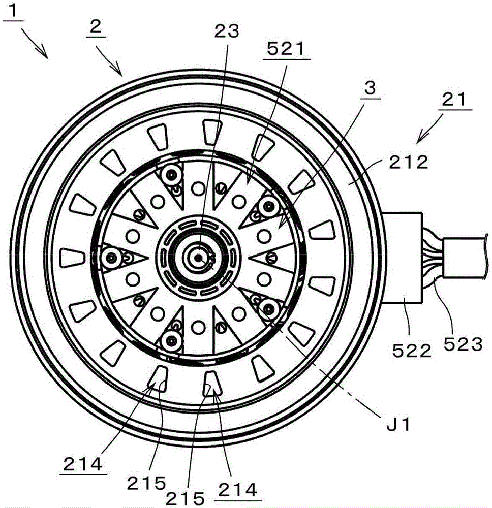
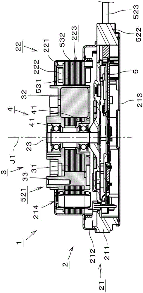
[0056] In this specification, the direction of the central axis J1 of the motor 1 figure 2 The upper side is simply referred to as "upper side", and the lower side is simply referred to as "lower side". In addition, the up-down direction does not indicate the positional relationship and direction when it is incorporated into an actual device. In addition, the direction parallel to the central axis J1 is referred to as "axial direction", the radial direction centered on the central axis J1 is simply referred to as "radial direction", and the circumferential direction centered on the central axis J1 is simply referred to as "circumferential direction". .

[0057] figure 1 It is a plan view showing a motor 1 according to an exemplary embodiment of the present invention. figure 2 is a longitudinal sectional view of the motor 1 . Parallel slanted lines in minute parts in the cross section are omitted. The motor 1 is an inner rotor type brushless motor. The motor 1 includes ...


PUM


Abstract

The invention relates to a motor. The motor comprises a rotary unit (3), a stationary unit (2) disposed around the rotary unit (3), and a bearing mechanism (4) which supports the rotary unit in a manner of rotatable relative to the stationary unit. The rotary unit (3) is provided with a plurality of magnets (32). The stationary unit is provided with a stator which is configured at the periphery of the rotary unit, and an outer cover which covers the upper surface of the stator and has conductivity. The stator is provided with a stator core and a coil. The stator core comprises a plurality of teeth and a core back. The coils are coiled on the stator core in a manner that an insulator is kept between the coil and the stator core. In overlook, the outer cover is provided with an opening at at least one circumferential clearance of the tooth. The outer cover is connected with a grounding potential.

Description

technical field [0001] The present invention relates to an electric motor. Background technique [0002] Conventionally, there are known motors with the following structure: an air suction hole and an air discharge hole are provided in the motor casing, and an air pressure difference is generated around the air suction hole and the air discharge port, and wind is generated inside the motor, and the air is emitted from the inside of the motor, especially is the heat of the stator and circuit board. [0003] For example, in the motor disclosed in US Patent No. 07977831, air holes are provided in the motor casing. Furthermore, the air pressure difference between the air suction hole at the bottom of the motor and the opening of the air gap is used to make wind flow inside the motor and dissipate the heat inside the motor from the air gap. [0004] Patent Document 1: US Patent No. 07977831 [0005] On the other hand, with the recent electrification of automobiles, many electr...

Claims


Application Information

Patent Timeline
Patent Type & Authority Applications(China)
IPC IPC(8): H02K5/04H02K1/27
CPCH02K9/06H02K21/16H02K1/2773H02K5/225H02K5/207
Inventor 古馆荣次藤原广树
Owner NIDEC CORP
Learn More