
A convenient ophthalmic surgical device

An ophthalmic surgery and convenient technology, applied in the field of medical devices, can solve problems such as affecting the safety and efficiency of surgery, increasing the risk of surgery, and visual fatigue of doctors, saving manpower, improving surgical efficiency, and reducing workload.

Inactive Publication Date: 2018-05-04
由新英
View PDF4 Cites 0 Cited by
  • Summary
  • Abstract
  • Description
  • Claims
  • Application Information

AI Technical Summary

Problems solved by technology

[0002] Medical equipment and instruments used by medical personnel are for the purpose of diagnosing and treating patients' diseases, making judgments on diseases, eliminating diseases, relieving illnesses, relieving pain, improving functions, prolonging life and helping patients recover. Diagnosis and treatment measures , Ophthalmic surgery is a very delicate operation that cannot tolerate the slightest deviation. At present, microsurgery is widely used in major hospitals at home and abroad. Doctors have visual fatigue, and at the same time, the height of each doctor is different. In this way, when performing surgery, the doctor needs to operate at different heights. Being in an uncomfortable working posture for a long time will cause discomfort to the doctor, increase the risk of surgery, and thus greatly increase the risk of surgery. It affects the safety and efficiency of the operation. When patients undergo surgery, the determined surgical angles are different, so the angles of patients on the operating table are also different. The optimal surgical angle can improve the success rate of the operation and make the patient's operation complete. Orientation, for this purpose, we propose a convenient-to-use ophthalmic surgery device

Method used


Image

  • A convenient ophthalmic surgical device
  • A convenient ophthalmic surgical device
  • A convenient ophthalmic surgical device

Examples


Embodiment Construction

[0014] The following will clearly and completely describe the technical solutions in the embodiments of the present invention with reference to the accompanying drawings in the embodiments of the present invention. Obviously, the described embodiments are only some, not all, embodiments of the present invention. Based on the embodiments of the present invention, all other embodiments obtained by persons of ordinary skill in the art without making creative efforts belong to the protection scope of the present invention.

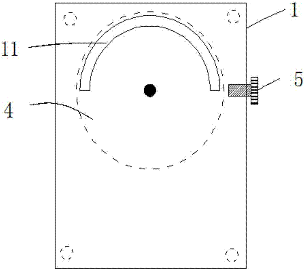
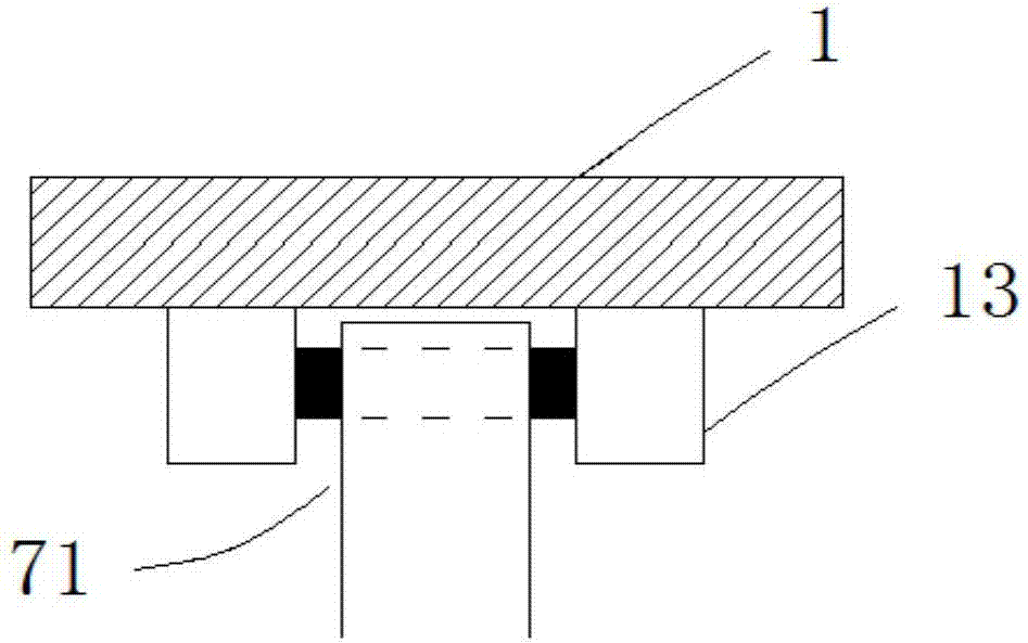
[0015] see Figure 1-3 , the present invention provides a technical solution: a convenient ophthalmic surgery device, comprising a body 1, the upper end of the body 1 is provided with a semicircular channel 11, and the middle part of the inner cavity of the body 1 is vertically provided with a central axis 2, And the central shaft 2 is sleeved with a bearing 3, the periphery of the bearing 3 is sleeved with a turntable 4, the periphery of the turntable 4 is pr...


PUM


Abstract

The invention discloses an ophthalmic surgery device convenient to use. The ophthalmic surgery device comprises a body, wherein a semicircular passage is arranged at the upper end of the body; a center shaft is vertically arranged in the middle of the inner chamber of the body, and is sleeved by a bearing; the bearing is sleeved by a rotary plate; a first supporting rod is vertically arranged on the rotary plate, and is inserted into the semicircular passage; a display is hinged to the top end of a second supporting rod; a limiting screw is arranged on the side wall of the body; an electron microscope lens is electrically connected with the display. According to the ophthalmic surgery device, through the adoption of the rotary plate, when a doctor is in all-directional surgery, the position of the device can be adjusted but the use precision cannot be influenced; through the synergistic effect of hydraulic rods and electromagnetic valves, a surgery bed can reach the optimal height needed by medical staff, so that the optimal angle of the surgery can be in the operation range of the medical staff all the time, and the efficiency and success rate of the surgery can be improved to the great extent.

Description

technical field [0001] The invention relates to the technical field of medical devices, in particular to a convenient ophthalmic operation device. Background technique [0002] Medical equipment and instruments used by medical personnel are for the purpose of diagnosing and treating patients' diseases, making judgments on diseases, eliminating diseases, relieving illnesses, relieving pain, improving functions, prolonging life and helping patients recover. Diagnosis and treatment measures , Ophthalmic surgery is a very delicate operation that cannot tolerate the slightest deviation. At present, microsurgery is widely used in major hospitals at home and abroad. Doctors have visual fatigue, and at the same time, the height of each doctor is different. In this way, when performing surgery, the doctor needs to operate at different heights. Being in an uncomfortable working posture for a long time will cause discomfort to the doctor, increase the risk of surgery, and thus greatly ...

Claims


Application Information

Patent Timeline
Patent Type & Authority Patents(China)
IPC IPC(8): A61G13/02A61G13/10
CPCA61G13/02A61G13/10A61G2203/10
Inventor 由新英李军
Owner 由新英
Learn More