Assembly device for internal combustion locomotive cooling chamber steel structures and manufacturing method thereof

A technology for diesel locomotives and cooling chambers, which is applied in the direction of manufacturing tools, auxiliary devices, vehicle components, etc., and can solve problems such as the inability to realize the interchangeability of the steel structure of the cooling chamber, the inability to completely correspond to the positions of the mounting holes, and the inability to guarantee the overall dimensions of the locomotive, etc. , to achieve the effect of promoting safe production, ensuring complete consistency, and saving manpower

Active Publication Date: 2016-03-16
CRRC DALIAN CO LTD
View PDF13 Cites 0 Cited by
  • Summary
  • Abstract
  • Description
  • Claims
  • Application Information

AI Technical Summary

Problems solved by technology

The steel structure of the cooling chamber is produced by this one-to-one research and matching process, which cannot realize the complete interchangeability of the steel structure of the cooling chamber, resulting in the inability to guarantee the overall dimensions of the locomotive when other steel structures of the cooling chamber are used for installation. There are often problems such as the position of the mounting holes cannot be completely matched, resulting in a lag in production progress and low production efficiency

Method used


Image

  • Assembly device for internal combustion locomotive cooling chamber steel structures and manufacturing method thereof
  • Assembly device for internal combustion locomotive cooling chamber steel structures and manufacturing method thereof
  • Assembly device for internal combustion locomotive cooling chamber steel structures and manufacturing method thereof

Examples


Embodiment Construction

[0026] In order to make the objectives, technical solutions and advantages of the present invention clearer, the technical solutions of the present invention are clearly and completely described below in conjunction with the drawings in the embodiments of the present invention. Obviously, the described embodiments are part of the implementation of the present invention. example, not all examples. Based on the embodiments of the present invention, all other embodiments obtained by persons of ordinary skill in the art without making creative efforts belong to the protection scope of the present invention.

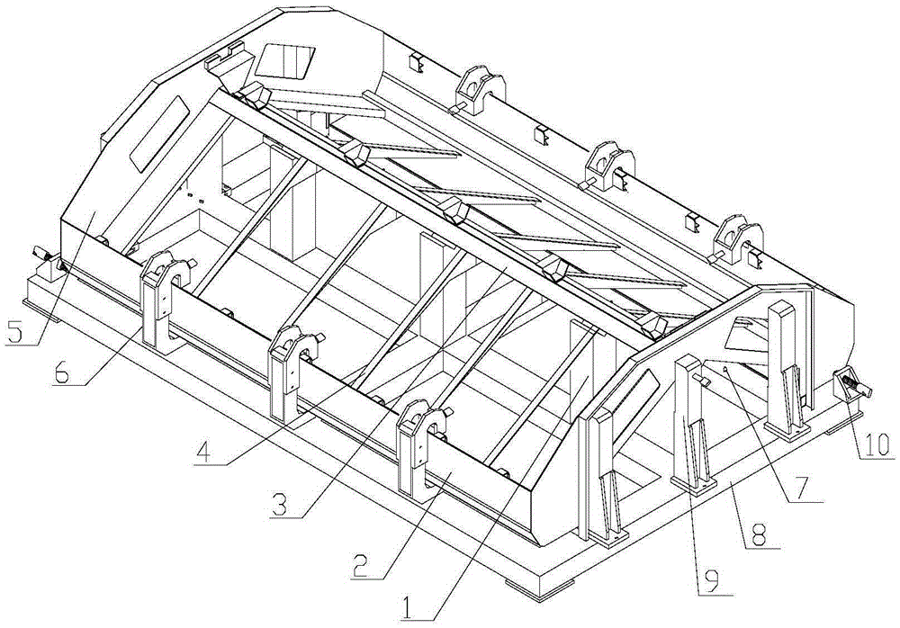
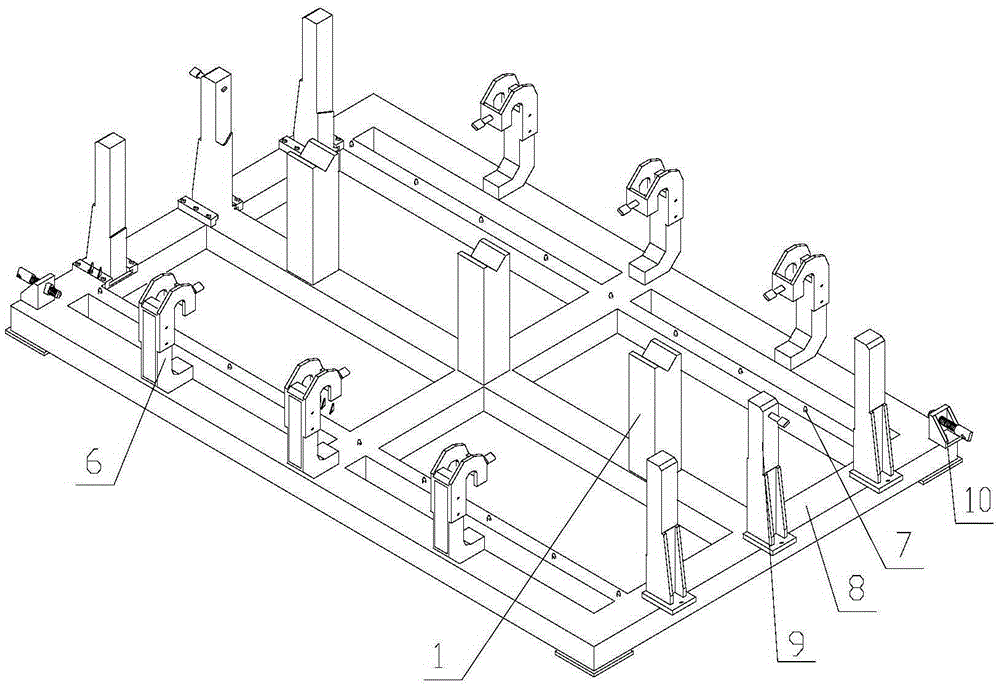
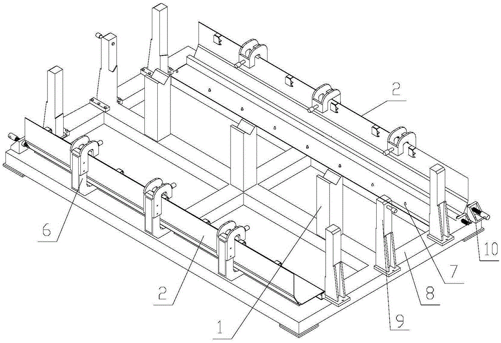
[0027] Referring to the accompanying drawings, the steel structure assembly equipment for the cooling chamber of a diesel locomotive according to the present invention has a base assembly 8 as a square frame structure with a "ten" beam in the center, and three partition wall positioning and tightening devices 9 are respectively installed and fixed on the left and right sides. ...


PUM


Abstract

The invention discloses an assembly device for internal combustion locomotive cooling chamber steel structures and a manufacturing method thereof. The assembly device is structurally characterized in that a base assembly is of a square frame structure with a linear beam in the center, partition locating and fastening devices are fixed to each of the left side and the right side of the base assembly, side plate locating and fastening devices shaped like hooks are installed on each of the upper side and the lower side of the base assembly, girder locating devices are fixed on a middle cross beam, locating pins are fixed to the upper plane of the base assembly, and fastening devices are installed at the opposite corners of the base assembly. By adopting the assembly device for the internal combustion locomotive cooling chamber steel structures and the manufacturing method thereof, the total uniformity of the contour dimensions of the manufactured cooling chamber steel structures is guaranteed, the interchange requirement of the cooling chamber steel structures is met, the operation is simple, convenient and fast, the requirement of mass production is met, the installation efficiency of final assemblies of locomotives is improved, the installation accuracy of the cooling chamber steel structures is guaranteed, the safety production is promoted, the labor intensity of staff is lowered, the manpower is saved, the working time is shortened, and the production efficiency is remarkably improved.

Description

technical field [0001] The invention relates to a steel structure of a diesel locomotive, in particular to a steel structure assembly equipment for a cooling chamber of a diesel locomotive and a manufacturing method thereof, belonging to the technical field of the diesel locomotive. Background technique [0002] In order to promote the long-term development of the railway industry, the technical performance and technical level of railway transportation equipment continue to put forward new requirements, and the continuous increase and upgrade of on-board equipment requires modular components that can be installed and disassembled independently to achieve interchangeability. The existing steel structure of the cooling chamber of a diesel locomotive is connected to the side wall of the locomotive body through bolts. In the final assembly of the locomotive, in order to be able to install the steel structure of the cooling chamber smoothly and at the same time ensure the overall...

Claims


Application Information

Patent Timeline
IPC IPC(8): B23K37/04
CPCB23K37/0443B23K2101/006
Inventor 赵希龙刘静柴晋峰徐海龙
Owner CRRC DALIAN CO LTD
Why Eureka
Try Eureka