Cabinet vacuum device

A vacuum cleaner, cabinet-type technology, applied in vacuum cleaners, exhaust diffusion devices, suction filters, etc., can solve the problems of small dust bucket capacity, weak air duct suction, complex structure, etc., to increase the dust bucket volume, prevent The effect of machine shaking and high air purification rate

Active Publication Date: 2018-07-10
GUANGDONG XINBAO ELECTRICAL APPLIANCES HLDG CO LTD
View PDF7 Cites 0 Cited by
  • Summary
  • Abstract
  • Description
  • Claims
  • Application Information

AI Technical Summary

Problems solved by technology

[0005] However, the inventor found in the process of implementing the present invention that the dust suction device of the prior art has the following disadvantages: relatively complex structure, weak air duct suction, high noise, too small capacity of the dust bucket, etc.

Method used


Image

  • Cabinet vacuum device
  • Cabinet vacuum device
  • Cabinet vacuum device

Examples


Embodiment Construction

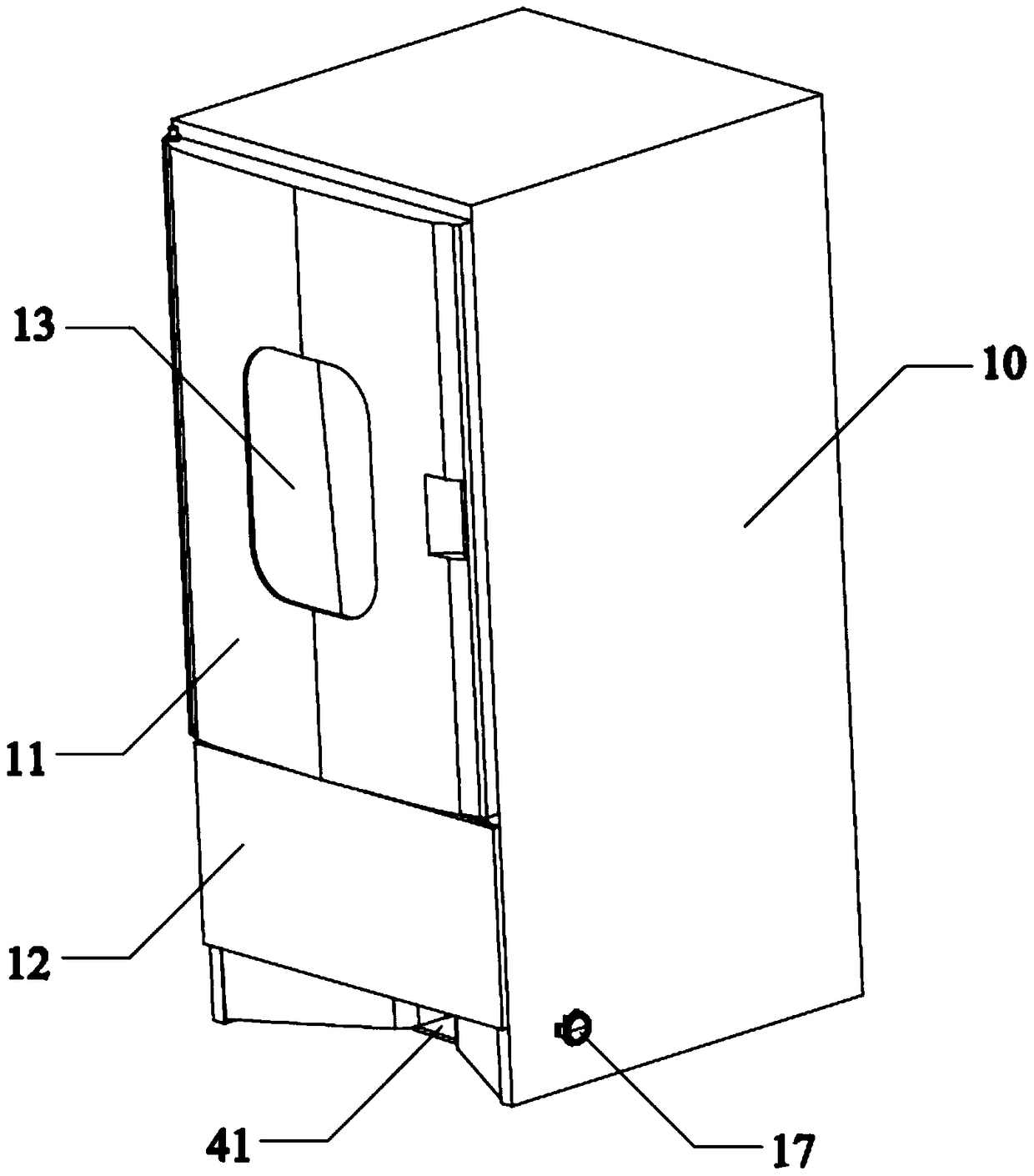
[0049] Refer below Figure 1-Figure 10 Describe in detail an embodiment of the cabinet type dust collection device provided by the present invention; as shown in the figure, this embodiment mainly includes:

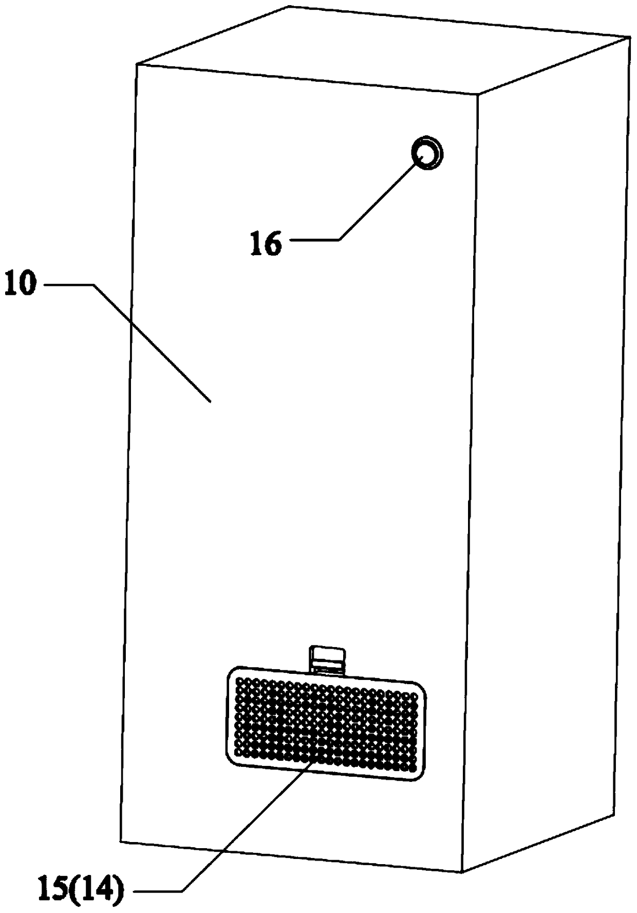
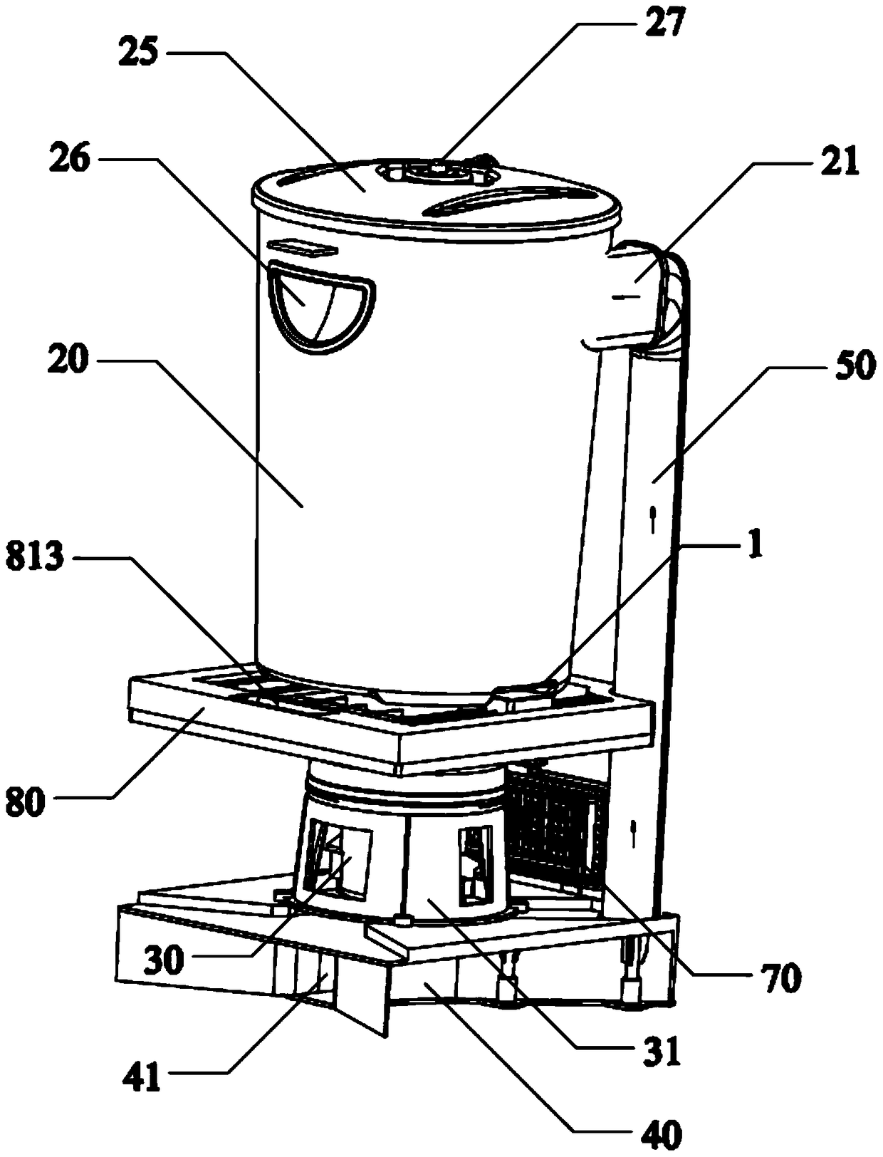
[0050] A cabinet body 10 with a switch door 11 is provided. The cabinet body 10 is provided with a dust bucket 20, a motor 30, and a suction base 40 with a suction port 41 in sequence from top to bottom, and the suction base 40 is installed vertically The air inlet duct 50 communicates with the air inlet 21 located at the top of the dust bucket 20;

[0051] The inside of the dust bucket 20 is provided with an air outlet duct 22 that is coaxial with the dust bucket 20 from the bottom up. The inside of the top of the bucket 20, so that an annular cyclone chamber is formed on the inner upper part of the dust bucket 20, and an annular dust collection chamber is formed on the inner bottom;

[0052] The top of the air outlet duct 22 communicates with the cyclone chamber throu...


PUM


Abstract

The invention discloses a cabinet type dust suction device. The cabinet type dust suction device comprises a cabinet body with an opening and closing door. A dust barrel, a motor and an air suction base with an air suction opening are sequentially arranged in the cabinet body from top to bottom, and the air suction base is communicated with an air inlet in the top of the dust barrel through a vertical air inlet pipeline. An air outlet pipeline which extends upwards from the bottom and is coaxial with the dust barrel is arranged in the dust barrel, the top end of the air outlet pipeline is sleeved with a filter sieve coaxial with the air outlet pipeline, and the top end of the filter sieve abuts against the inner side of the top of the dust barrel, so that an annular vortex chamber is formed in the inner upper portion of the dust barrel, and an annular dust collection chamber is formed in the inner bottom of the dust barrel. The top end of the air outlet pipeline is communicated with the vortex chamber through the filter sieve, and the bottom end of the air outlet pipeline is communicated with an air outlet in the surface of the cabinet body through the motor and space around the motor. The cabinet type dust suction device has large suction force, an ultra-low-noise effect and a higher air purification rate and is more optimized and more reasonable in structure; the volume of the dust barrel can be effectively increased; the device can be effectively prevented from shaking and is more stable in performance and longer in service life.

Description

technical field [0001] The invention relates to dust collection technology, in particular to a cabinet type dust collection device. Background technique [0002] In recent years, with the continuous development of industry, the natural environment has been severely damaged, and there are more and more dust and particles in the air. Human beings have continuously strengthened their awareness of environmental protection. To classify garbage, it is necessary to clean up garbage Taking into account the secondary pollution of the environment, it is an increasingly serious problem. [0003] In people's daily garbage cleaning work, hair and dust have become the main garbage that needs to be cleaned frequently or frequently and is inconvenient to handle in people's daily life; Man headache problem. [0004] In order to reduce the workload of daily garbage cleaning, a type of vacuum device mainly for collecting hair and dust came into being, because it can conveniently collect hair...

Claims


Application Information

Patent Timeline
Patent Type & Authority Patents(China)
IPC IPC(8): A47L5/16A47L9/00A47L9/16
CPCA47L5/16A47L9/0081A47L9/1616A47L9/1666A47L9/1683
Inventor 郭建刚
Owner GUANGDONG XINBAO ELECTRICAL APPLIANCES HLDG CO LTD
Why Eureka
Try Eureka