
Vacuum storage device

A storage and vacuum technology, applied in the field of storage containers, can solve the problems of poor thermal insulation effect, unsuitable long-term storage of items, temperature changes of stored items, etc., and achieve the effect of enhancing sealing performance

Inactive Publication Date: 2016-03-09
NANCHENG HANRUI IND CO LTD
View PDF10 Cites 1 Cited by
  • Summary
  • Abstract
  • Description
  • Claims
  • Application Information

AI Technical Summary

Problems solved by technology

[0002] At present, most of the vacuum storage containers produced on the market are single-layer containers, which mainly have the function of keeping fresh and antibacterial. Since the stored objects only directly contact the outside through a single layer of material, it is easy to cause changes in the temperature of the stored objects and lose their taste.
[0003] At the same time, the double-layer containers with thermal insulation function on the market all have a closed vacuum compartment between the inner and outer layers, and the storage is placed inside, separated from the outside by the vacuum compartment, which slows down the speed of temperature transfer, thereby playing the role of heat preservation , but for the stored items in the inner layer, there is no way to keep fresh and sterilize; and after a long time of use, the sealing effect of the vacuum compartment will gradually decrease, resulting in worse and worse heat preservation effect, which is not suitable for long-term storage of items. store

Method used


Image

  • Vacuum storage device
  • Vacuum storage device
  • Vacuum storage device

Examples


Embodiment Construction

[0022] The present invention will be further described below in conjunction with the accompanying drawings and specific embodiments, but not as a limitation of the present invention.

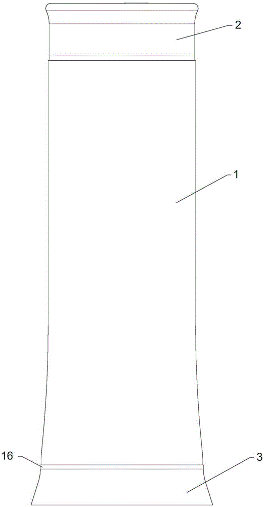
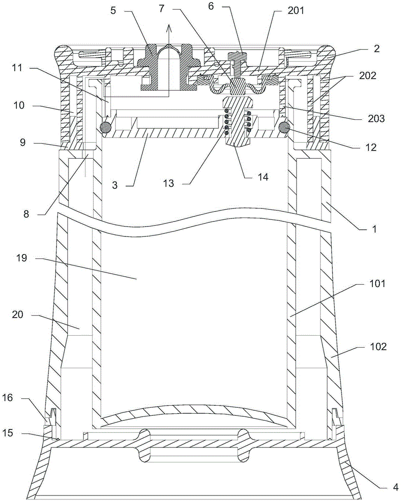
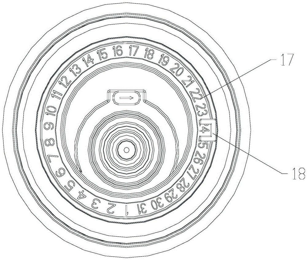
[0023] like Figure 1 to Figure 3 As shown, a vacuum storage device includes a cup body 1, a top cover 2, an inner cover 3, and a bottom cover 4. The cup body 1 is composed of an integrally formed inner container 101 and an outer container 102. The inner container 101 It is a cylinder with an open top, the outer tank 102 is open at the bottom, and the top cover 2 is detachably covered at the top opening of the inner tank 101. The top cover 2 includes a top wall 201, an outer side wall 202, and an inner side wall. 203, there is a gap between the inside of the top wall 201 and the top of the liner 101, the top wall 201 is provided with an air pumping pad 5, a push twist 6, and a time recording device, and the inside of the top wall 201 is fixed with the The elastic valve 7 used in conjunction wit...


PUM


Abstract

The invention relates to a vacuum storage device which comprises a cup body, a top cover, an inner cover and a bottom cover. The cup body is composed of an inner lining and an outer lining which are formed integrally. The inner lining is a cylinder with the top open. The bottom of the outer lining is open. An opening in the top of the inner lining is detachably covered with the top cover. The top cover comprises a top wall, an outer side wall and an inner side wall. An exhaust cushion and a push button are arranged on the top wall. An elastic valve used in cooperation with the push button is fixed to the inner side of the top wall. At least one first through hole is formed in the top of the outer lining. The first through hole is located between the outer side wall and the inner lining. The top of the outer lining is covered with the outer side wall through a first sealing ring. The inner cover is fixed to the bottom of the inner side wall. An I-shaped air valve which can be restored through a spring is arranged on the inner cover. An opening in the bottom of the outer lining is covered with the bottom cover in a sealed mode. According to the vacuum storage device, both the heat preservation function and the freshness preservation and bacteriostasis function are achieved, the sealing performance is good, and the vacuum storage device is suitable for storing objects for a long time.

Description

technical field [0001] The invention relates to a storage container, in particular to a vacuum storage device. Background technique [0002] At present, most of the vacuum storage containers produced on the market are single-layer containers, which mainly have the function of keeping fresh and antibacterial. Since the stored objects are only in direct contact with the outside world through a single layer of material, it is easy to cause changes in the temperature of the stored objects and lose their taste. [0003] At the same time, the double-layer containers with thermal insulation function on the market all have a closed vacuum compartment between the inner and outer layers, and the storage is placed inside, separated from the outside by the vacuum compartment, which slows down the speed of temperature transfer, thereby playing the role of heat preservation , but for the stored items in the inner layer, there is no way to keep fresh and sterilize; and after a long time of...

Claims


Application Information

Patent Timeline
IPC IPC(8): B65D81/20B65D8/06B65D51/16B65D51/24
CPCB65D7/22B65D51/1683B65D51/24B65D81/2038B65D2251/20
Inventor 官学峰
Owner NANCHENG HANRUI IND CO LTD
Learn More