
Single clutch multi-stage automatic transmission

A technology of automatic transmission and one-way clutch, which is applied in transmission control, components with teeth, belts/chains/gears, etc. It can solve the problems of shifting interference, many control programs, and a large number of actuators, etc., and achieve improvement Simple and smooth shifting speed and shifting procedure

Inactive Publication Date: 2017-11-28
解利
View PDF5 Cites 0 Cited by
  • Summary
  • Abstract
  • Description
  • Claims
  • Application Information

AI Technical Summary

Problems solved by technology

[0002] At present, common transmissions, taking automobiles as an example, are divided into manual and automatic transmissions. Automatic transmissions are divided into stepless, automatic, dual-clutch, parallel shaft and AMT automatic transmissions. When changing gears, the number of actuators is large and each gear The switching process between gears is complicated, and there are many control programs, which are easy to cause shifting interference between gears and high failure rate.

Method used


Image

  • Single clutch multi-stage automatic transmission
  • Single clutch multi-stage automatic transmission

Examples


Embodiment 1

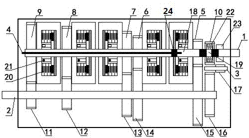
[0021] Such as figure 1 As shown, the power input shaft 1 is equipped with a plurality of driving gears, each driving gear corresponds to a gear position, and the power output shaft 2 is equipped with a plurality of driven gears, and each driven gear corresponds to a gear position; In this embodiment, there are 5 forward gears, and 5 driving gears are installed on the corresponding power input shaft, that is, the first gear driving gear 5, the second gear driving gear 6, the third gear driving gear 7, and the fourth gear driving gear. Gear 8, the fifth gear driving gear 9; the power output shaft 2 is equipped with 5 driven gears correspondingly, that is, the first gear driven gear 15, the second gear driven gear 14, the third gear driven gear 13, the Fourth gear driven gear 12, fifth gear driven gear 11.

[0022] The power input shaft 1 is provided with a shift shaft 4, and one end of the shift shaft is fixed with a piston 24, and the outer side of the piston is a first oil p...

Embodiment 2

[0029] In the second embodiment, the shift shaft is arranged in the power output shaft, and the one-way clutch and the clutch are arranged in the driven gear, and the rest of the structure and working principle are the same as in the first embodiment.

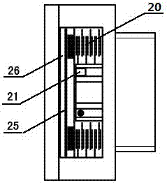
[0030] There is a shift shaft inside the power output shaft, and a piston is fixed at one end of the shift shaft, and the outer chamber of the piston is the third oil pressure chamber for controlling shift; each driven gear is equipped with a one-way clutch and a clutch , the clutch can be controlled by the oil pressure of the third oil pressure chamber to be in the combined state, and the driven gear drives the power output shaft to rotate through the clutch. The one-way clutch in the driven gear is installed on the power output shaft, and the clutch is located on the outside of the one-way clutch; there is also a clutch oil chamber and a clutch piston in the driven gear, and the clutch oil chamber can be connected with the thi...


PUM


Abstract

The invention relates to a single-clutch and multi-level automatic transmission. A power input shaft (1) is provided with a plurality of drive gears. Each drive gear corresponds to one gear. A plurality of driven gears are correspondingly arranged on a power output shaft (2), and each driven gear corresponds to one gear. The single-clutch and multi-level automatic transmission is characterized in that the power input shaft (1) is internally provided with a gear shifting shaft (4), a piston (24) is fixed to one end of the gear shifting shaft (4), and a first oil pressure cavity (18) used for controlling gear shifting is formed in the outer side of the piston (24); each drive gear is internally provided with a one-way clutch (21) and a clutch (20), wherein the clutch (20) can be controlled by oil pressure of the first oil pressure cavity (18) to be in a combined state; and the power input shaft (1) drives the work ends of the drive gears to rotate through the clutches (20), and the work ends of the drive gears are engaged with the driven gears on the power output shaft.

Description

technical field [0001] The invention relates to the technical field of mechanical torque power transmission for automobiles, ships, aviation, etc., in particular to a single-clutch multi-stage automatic transmission. Background technique [0002] At present, common transmissions, taking automobiles as an example, are divided into manual and automatic transmissions. Automatic transmissions are divided into stepless, automatic, dual-clutch, parallel shaft and AMT automatic transmissions. When changing gears, the number of actuators is large and each gear The switching process between gears is complicated, and there are many control programs, which are prone to problems such as shifting interference between gears and high failure rate. Contents of the invention [0003] The object of the present invention is to provide a single-clutch multi-stage automatic transmission, which has fewer shift actuators, simple shift procedure, effectively solves the problem of shift interferen...

Claims


Application Information

Patent Timeline
Patent Type & Authority Patents(China)
IPC IPC(8): F16H61/28
Inventor 解利薛庆文梅天放
Owner 解利
Learn More