
In-pipe circular hole chamfering machine

A technology of chamfering machine and round hole, which is applied in the direction of metal processing machinery parts, driving devices, metal processing equipment, etc., can solve the problems of low chamfering precision, high labor intensity, difficult operation, etc., and achieve convenient operation, chamfering The effect of high precision and low labor intensity

Inactive Publication Date: 2016-02-24
XINCHANG COUNTY YULIN STREET QUANSHUN MACHINERY PLANT
View PDF5 Cites 4 Cited by
  • Summary
  • Abstract
  • Description
  • Claims
  • Application Information

AI Technical Summary

Problems solved by technology

The chamfering in the hole of the prior art is generally performed by hand, and it is difficult to chamfer some narrow positions, such as the round hole in the pipe, and the manual operation has the problems of difficult operation, high labor intensity, and low chamfering precision, which cannot be adapted to The mass production requirements of the product cannot meet the quality and accuracy requirements of the product

Method used


Image

  • In-pipe circular hole chamfering machine
  • In-pipe circular hole chamfering machine
  • In-pipe circular hole chamfering machine

Examples


Embodiment Construction

[0012] The following will clearly and completely describe the technical solutions in the embodiments of the present invention with reference to the accompanying drawings in the embodiments of the present invention. Obviously, the described embodiments are only some of the embodiments of the present invention, not all of them. Based on the embodiments of the present invention, all other embodiments obtained by persons of ordinary skill in the art without making creative efforts belong to the protection scope of the present invention.

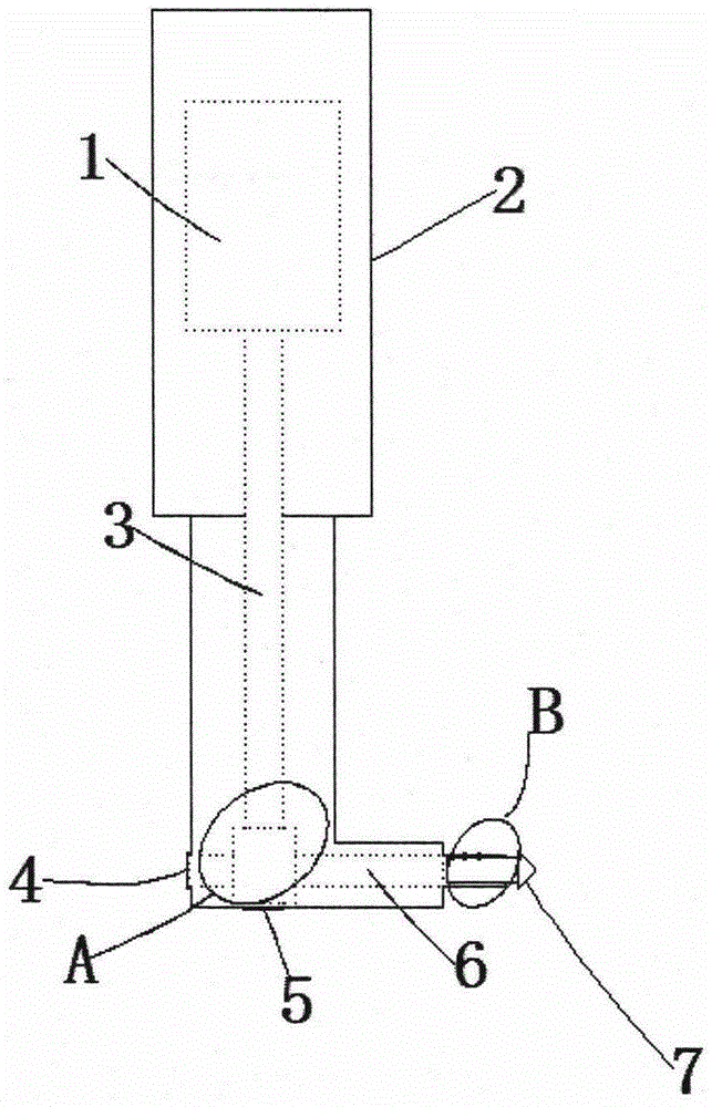
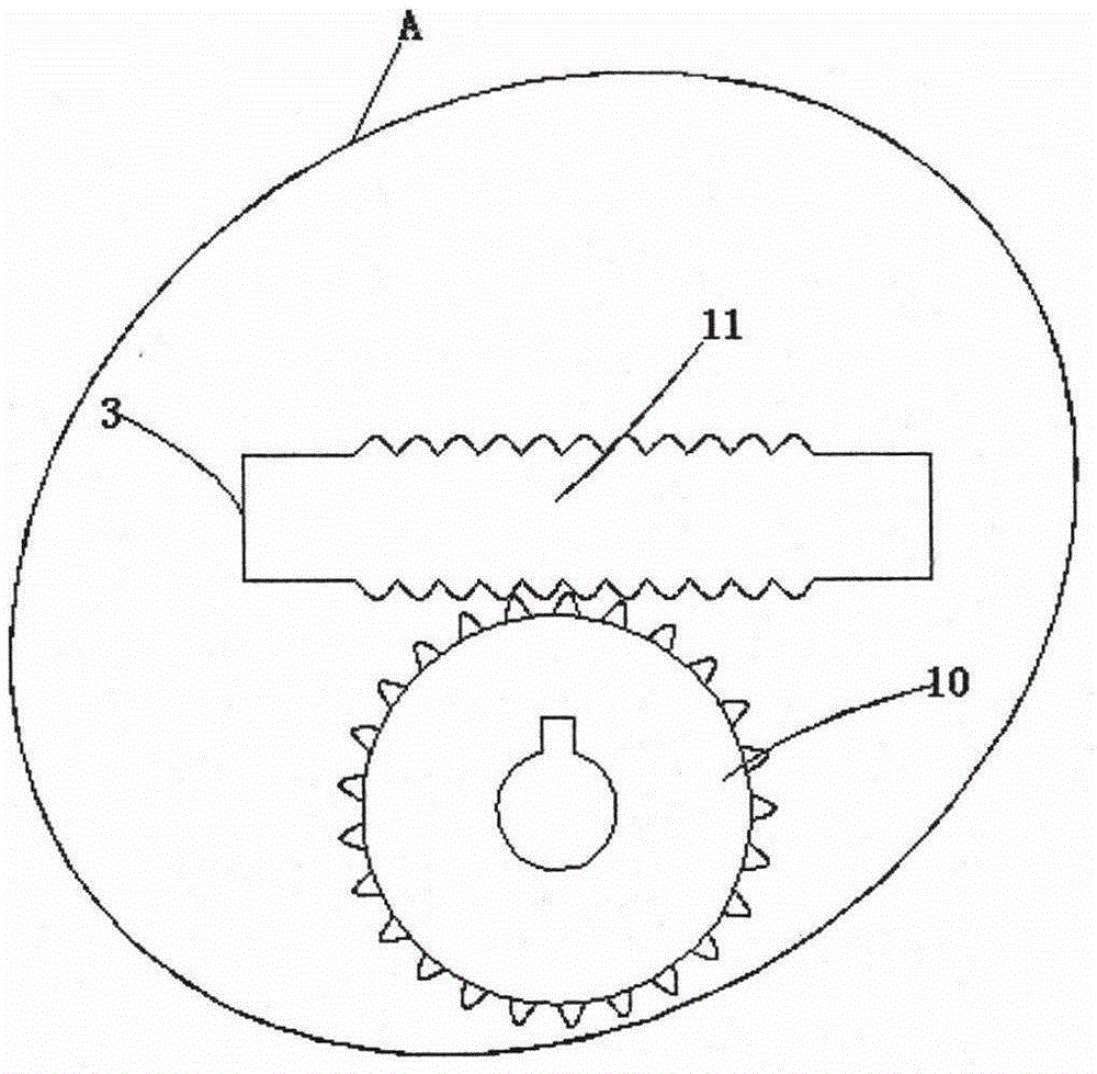
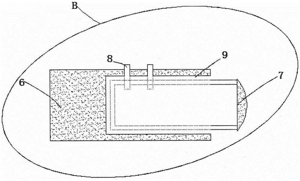
[0013] see Figure 1-3 , the present invention provides a technical solution: a round hole chamfering machine in a pipe, comprising a housing 2 and a chamfering cutter head 7, a driving motor 1 is arranged on the upper part of the inner cavity of the housing 2, and the rotating shaft of the driving motor 1 is connected to the first One end of the drive shaft 3 is fixedly connected, the other end of the first drive shaft 3 has an integrally formed...


PUM


Abstract

The invention discloses an in-pipe circular hole chamfering machine which comprises a housing and a chamfering cutter head, wherein a driving motor is arranged at the upper part of an inner cavity of the housing; a rotating shaft of the driving motor is fixedly connected with one end of a first driving shaft; a worm molded integrally is arranged at the other end of the first driving shaft; a first rolling bearing is arranged at the side wall of the inner cavity of the housing; a second rolling bearing is arranged at the bottom of the inner cavity of the housing; the bottom of the worm is connected with the inner cavity of the second rolling bearing in an inserting manner; the inner cavity of the first rolling bearing is connected with a second driving shaft in an inserting manner; a turbine matched with the worm is mounted on the left side of the second driving shaft; a groove is formed in the right side of the second rolling bearing; the left side of the chamfering cutter head is connected with an inner cavity of the groove in an inserting manner; and the chamfering cutter head is in bolted connection with the groove through bolts. Compared with the conventional chamfering machine, the in-pipe circular hole chamfering machine allows a worker to carry out in-pipe circular hole chamfering operation more conveniently, the labor intensity is low, and the chamfering accuracy is high.

Description

technical field [0001] The invention relates to the technical field of machining, in particular to a chamfering machine for round holes in pipes. Background technique [0002] During the machining process, through holes, blind holes, oblique holes, and long holes often need to be provided inside the housing, and these through holes, blind holes, oblique holes, and elongated holes often need to be chamfered to remove burrs. The chamfering in the hole of the prior art is generally performed by hand, and it is difficult to chamfer some narrow positions, such as the round hole in the pipe, and the manual operation has the problems of difficult operation, high labor intensity, and low chamfering precision, which cannot be adapted to The mass production requirements of the product cannot meet the quality and accuracy requirements of the product. Contents of the invention [0003] The object of the present invention is to provide a pipe inner circular hole chamfering machine to ...

Claims


Application Information

Patent Timeline
Patent Type & Authority Applications(China)
IPC IPC(8): B23D79/04B23Q5/10
CPCB23D79/04B23Q5/10
Inventor 竺林坤石伟东
Owner XINCHANG COUNTY YULIN STREET QUANSHUN MACHINERY PLANT
Learn More