Correction in slit-scanning phase contrast imaging

一种相位衬度成像、狭缝扫描的技术,应用在成像装置、用于放射诊断的仪器、使用辐射衍射的材料分析等方向,能够解决条纹轮廓不像等问题,达到增强图像质量的效果

Inactive Publication Date: 2016-02-17
KONINKLIJKE PHILIPS NV
View PDF4 Cites 12 Cited by
  • Summary
  • Abstract
  • Description
  • Claims
  • Application Information

AI Technical Summary

Problems solved by technology

However, the obtained fringe profile may not look like the ideal fringe pattern

Method used


Image

  • Correction in slit-scanning phase contrast imaging
  • Correction in slit-scanning phase contrast imaging
  • Correction in slit-scanning phase contrast imaging

Examples


Embodiment Construction

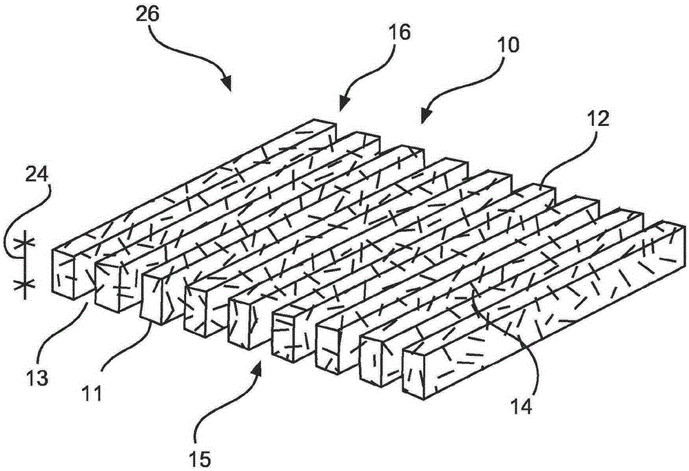
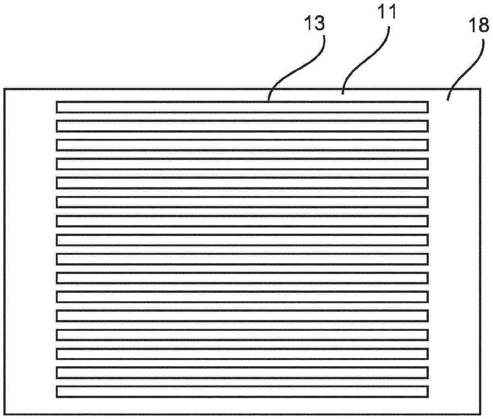
[0073] Figure 1A shows a calibration filter grating 10 for an X-ray phase contrast imaging device. The calibration filter grating 10 comprises a first plurality of filter segments 11 comprising filter material 12 . The filter material 12 is made of a material with structural elements 14 , which are only schematically shown in FIG. 1A , not to scale, comprising structural parameters on the order of micrometers. Furthermore, a second plurality of opening segments 13 is provided. Filter segments 11 and opening segments 13 are arranged alternately in a filter pattern 15 . The calibration filter grating 10 is configured to be movably arranged between the X-ray source grating and the analysis grating of the interferometer unit in the slit scanning system of the phase contrast imaging device, which will also be relative to Figure 2 to Figure 6 It will be described in more detail. The filter pattern 15 is configured to align with the slit pattern of the slit scanning system (see a...


PUM


Abstract

The present invention relates to calibration in X-ray phase contrast imaging. In order to remove the disturbance due to individual gain factors, a calibration filter grating (10) for a slit-scanning X-ray phase contrast imaging arrangement is provided that comprises a first plurality of filter segments (11) comprising a filter material (12) and a second plurality of opening segments (13). The filter segments and the opening segments are arranged alternating as a filter pattern (15). The filter material is made from a material with structural elements (14) comprising structural parameters in the micrometer region. The filter grating is movably arranged between an X-ray source grating (54) and an analyzer grating (60) of an interferometer unit in a slit-scanning system of a phase contrast imaging arrangement. The slit-scanning system is provided with a pre-collimator (55) comprising a plurality of bars (57) and slits (59). The filter pattern is aligned with the pre-collimator pattern (61).

Description

technical field [0001] The present invention relates to calibration in slit scanning X-ray phase contrast imaging, in particular to a calibration filter grating for a slit scanning X-ray phase contrast imaging device, a slit scanning X-ray phase contrast An imaging device, an X-ray imaging system and a method for calibration in slit scanning X-ray phase contrast imaging, as well as a computer program element and a computer readable medium. Background technique [0002] For phase contrast imaging based on slit scanning, eg for differential phase contrast imaging (DPCI), a required preprocessing step is flat-field correction in imaging applications. DPCI is an emerging technique that has the potential to improve the diagnostic value of X-ray imaging. A DPCI system can be provided with three gratings used between the X-ray source and the detector. Several x-ray images are required to be acquired at different relative positions of the two gratings close to the detector. Since...

Claims


Application Information

Patent Timeline
Patent Type & Authority Applications(China)
IPC IPC(8): A61B6/00G01N23/20G21K1/06G02B5/18
CPCA61B6/484G01N23/20075G02B5/1838G21K1/06G01N2223/303A61B6/5258A61B6/583G21K1/10G21K2207/005A61B6/582
Inventor E·勒斯尔G·马滕斯
Owner KONINKLIJKE PHILIPS NV
Why Eureka
Try Eureka